Functional description – Comtech EF Data LCS-4 User Manual
Page 16
LCS-4 L-Band Combiner Switch
Revision 1
Introduction
MN/LCS4.IOM
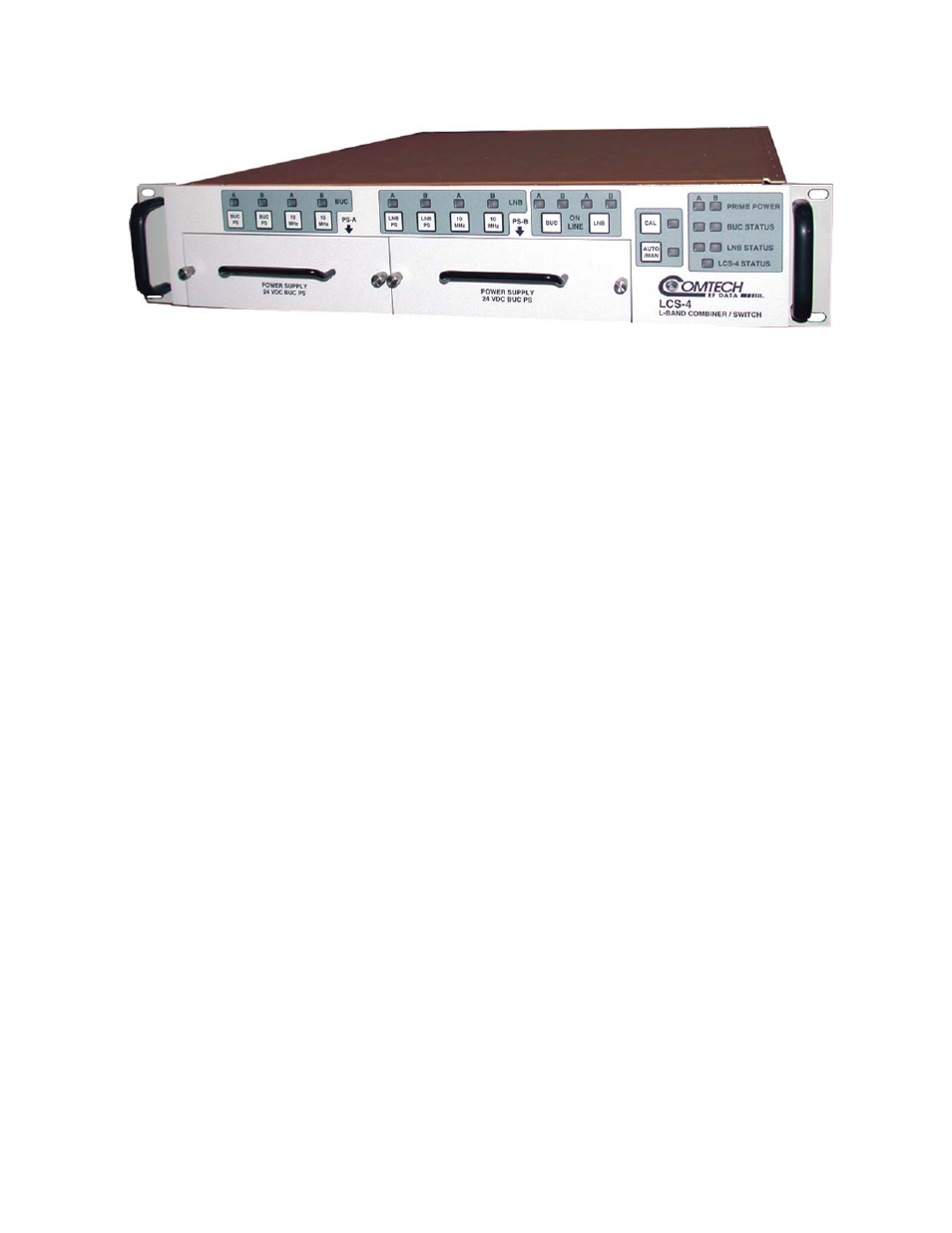
Figure 1-1. LCS-4 L-Band Combiner Switch
1.2 F
UNCTIONAL
D
ESCRIPTION
On the TX-side, the TX signals of up to four modems are combined. The combined output is
transmitted to one of the two outputs that feed an antenna system. Each TX output provides a
10 MHz BUC reference signal, a BUC power supply, and FSK communications. Each 10 MHz
BUC reference and power supply has an independent On/Off control. Figure 1-2 shows a block
diagram of the unit.
On the RX-side, one of the two antenna systems feed a splitter. The splitter outputs provide the
RX signal for up to four modem receivers. Each RX input provides a 10 MHz LNB reference
signal, a LNB power supply, and DESQ communications. Each 10 MHz LNB reference and
power supply has an independent On/Off control. The L-Band Multi-Modem has redundant
internal power supplies, BUC power supplies, and LNB power supplies. L-Band Multi-Modem
Module also provides a driver for an RF (baseball) switch.
1–2