System installation (rs-301 switch installed), Connect system installation with rs-301 switch – Comtech EF Data SMS-301 User Manual
Page 99
SMS-301 Redundancy Switch
SDM-300/-300A System Installation
Rev. 3
B–5
B.1.2
System Installation (RS-301 Switch Installed)
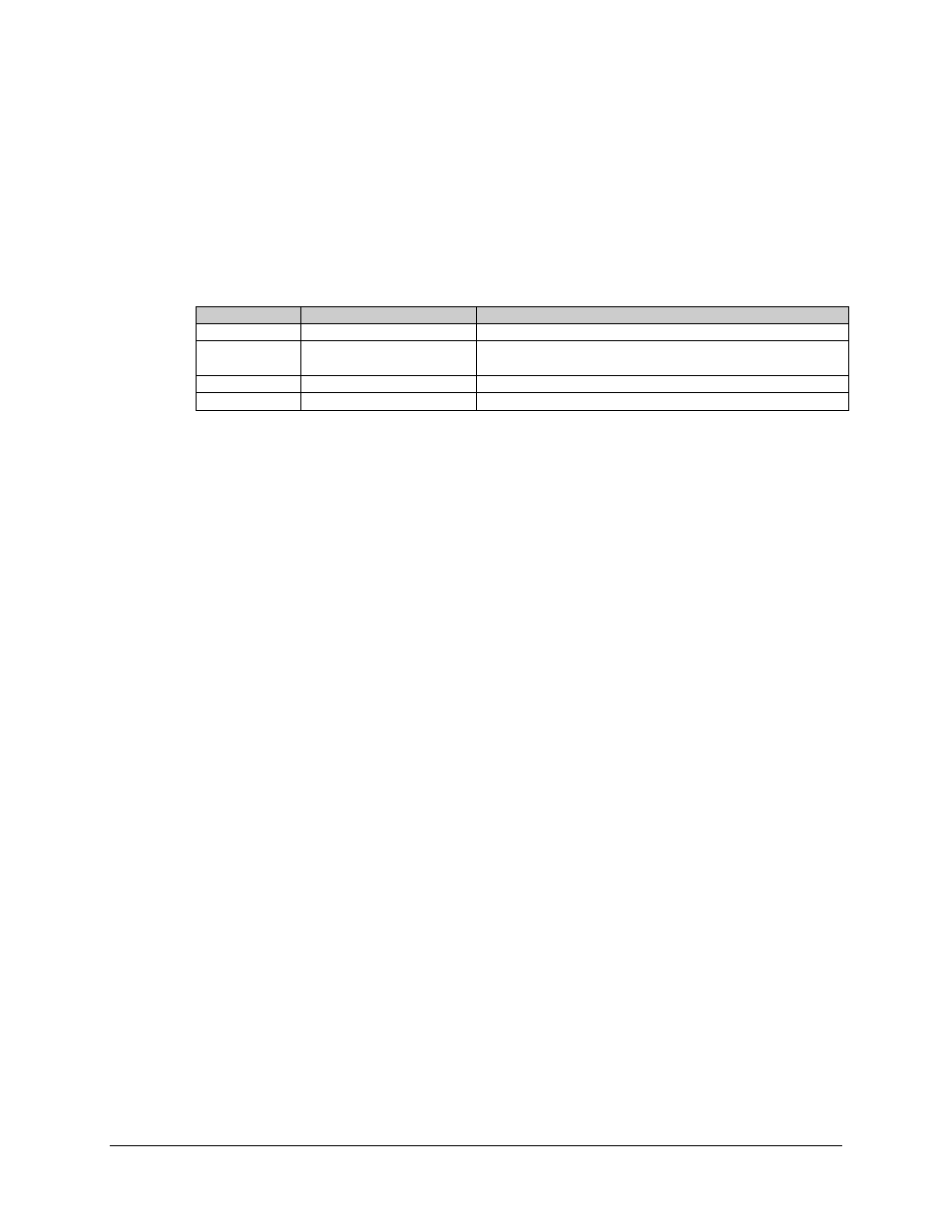
After unpacking the 1:1 switch and the RS-301 Remote Switch, refer to Table B-2 and
the following instructions.
Table B-2. RS-301 Configuration Cabling
Item No.
Part No.
Description
1
PL/CA90101G100-4
Data Cable, 100-pin
2
PL/0813-4
PL/0813-8
BNC Cable, 48.0
± 1.5 inches (length)
BNC Cable, 96.0
± 3.0 inches (length)
3
PL/6239
Cable Assy, Remote Control with Termination
4
PL/6051-1
Power Cable Assemblies
B.1.3
Connect System Installation with RS-301 Switch
Refer to Figure B-2 for cabling with the RS-301 Switch installed.
1. Mount the 1:1 switch in a standard equipment rack with four bolts.
2. Mount the remote switch (RS-301) in the same rack using four bolts.
3.
Connect the Data I/O interface as follows:
a.
Connect the “RREMOTE SWITCH CONTROL” connector (J1) to the
“SWITCH CONTROL INTERFACE” connector (J16) on the RS–301
switch, using cabling PL/CA90101G100-4.
b.
Connect the ‘MODEM A DATA” connectopr (J14) on the RS-301 switch to
the prime modulator Data I/O connector, using Cable PL/CA90101G100-4
c.
Connect the “MODEM B DATA” connector (J15) on the remote switch to
the backup modulator Data connector, using Cabling PL/90101G100-4.
4.
Connect the MOD side of the 1:1 switch as follows:
a.
Connect the “TX IF” BNC connector (J4) in the 1:1 switch rear panel to the
top converter IF IN (J7), using Cable PL/0813-X.
b.
Connect the “A” BNC connector (J5) to the prime modem “TX IF OUT”
(CP1), using Cable PL/0813-X.
c.
Connect the “B” BNC connector (J6) to the backup modem “TX IF OUT”
(CP1), using Cable PL/0813-X.