Remote switch (rs-301) option, 3 remote switch (rs-301) option – Comtech EF Data SMS-301 User Manual
Page 71
SMS-301 Redundancy Switch
Theory of Operation
Rev. 3
4-5
4.3
Remote Switch (RS-301) Option
The application for this option is to provide access to tributary data, via the remote
switch, when the 1:1 switch is used with two SDM-300/-300A Satellite Modems that are
configured for the 8-Channel MUX option.
For this option an extender board (AS/6542) replaces the switch board that normally
resides within the 1:1 switch. This extender board interfaces with the M&C motherboard
and provides control signals, power and ground to an external data switch (RS-301).
The remote switch (RS-301) provides the user with connections for eight tributary
channels (EIA-422, EIA-232 data and clock) and one connection for auxiliary data. This
switch, under M&C control, will switch data (only) between the prime modem and/or the
backup modem, and the customer-data interface. The TX IF switching remains internal to
the 1:1 switch.
The M&C automatically detects this switch option and presents this information, via the
front panel display, under Interface Type in the Utility System menu.
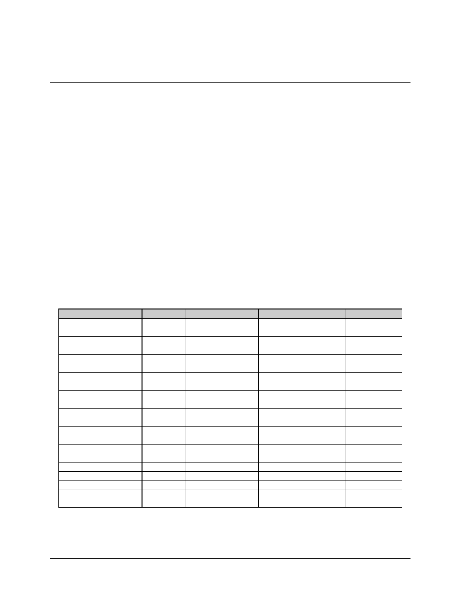
The connectors for the remote switch are listed in Table 4-1.
Table 4-1. Remote Switch (RS-301) Connectors
Name
REF DES
Connector Type
Function
Table Reference
TRIBUTARY 1 DATA
J1
15-pin D
EIA-422 or EIA-232
TRIB 1 Clock and Data
TRIBUTARY 2 DATA
J2
15-pin D
EIA-422 or EIA-232
TRIB 2 Clock and Data
TRIBUTARY 3 DATA
J3
15-pin D
EIA-422 or EIA-232
TRIB 3 Clock and Data
TRIBUTARY 4 DATA
J4
15-pin D
EIA-422 or EIA-232
TRIB 4 Clock and Data
TRIBUTARY 5 DATA
J5
15-pin D
EIA-422 or EIA-232
TRIB 5 Clock and Data
TRIBUTARY 6 DATA
J6
15-pin D
EIA-422 or EIA-232
TRIB 6 Clock and Data
TRIBUTARY 7 DATA
J7
15-pin D
EIA-422 or EIA-232
TRIB 7 Clock and Data
TRIBUTARY 8 DATA
J8
15-pin D
EIA-422 or EIA-232
TRIB 8 Clock and Data
AUX
J9
15-pin D
Auxiliary Data
MODEM A DATA
J14
100-pin Miniature D
Modem A Data I/O
MODEM B DATA
J15
100-pin Miniature D
Modem B Data I/O
SWITCH CONTROL
INTERFACE
J16
37-pin D
Control Signals, Power and
Ground