Description, Description (standard configuration) – Comtech EF Data SMS-301 User Manual
Page 16
Introduction
SMS-301 Redundancy Switch
1–2
Rev. 3
1.1 Description
1.1.1
Description (Standard Configuration)
The 1:1 switch is a fully automated protection switch for Comtech EFData satellite
modems, providing redundancy for one prime modem using one identical backup
modem. Common interfaces are provided for user data terminal equipment and
uplink/downlink RF equipment, as well as the primary and redundant (backup) modems.
The integrated uplink 1:1 switch and downlink splitter operate at IF frequencies in the
range of 50 to 180 MHz.
Full Monitor and Control (M&C) functions are supported by an integrated
microprocessor system. The M&C system is designated to maintain the 1:1 switch
configuration settings in non-volatile memory for at least one year without prime power.
Note: While 1:1 switch prime power is not applied, the default connections are to
Modem A.
Remote control is provided by an EIA-485 or EIA-232 interface located on the rear panel
of the chassis. The rear panel also is the location for all external interconnections. The
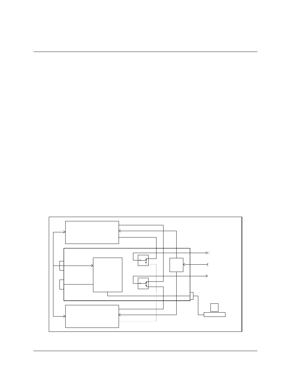
1:1 switch is enclosed in a single unit, 19-inch (48.3 cm) rack-mounted chassis. Figure 1-2
illustrates the system block diagram.
M O D E M A
M O D E M A
M O D E M R EM O T E
J1 3
J1 4
E IA -4 85
S TATU S /FA U LTS
S W IT C H M &C LO G IC
R E M O TE
C O N T R O L
1 FO R 1 SW ITCH
T R A N SM IT IF
R E C E IV E IF
B A S EB A N D D ATA
T X/R X
T R A N SM IT IF
R E C E IV E IF
B A S EB A N D D ATA
T X/R X
J1
B A S EB A N D D ATA
TO /F R O M C U S TO M E R
R E C E IV E IF
50 TO 18 0 M H z F R O M
D O W N C O N V E RTE R
T R A N SM IT IF
50 TO 18 0 M H z
TO U P C O N VE RT E R
J8
J4
J1 0
E IA -2 32 O R
EIA-48 5
J7
J6
J3
J9
J5
J2
S P LIT TE R
H O T T E R M IN A L
O R C O M P U T E R
Figure 1-2. System Block Diagram (Standard Configuration)