Description (with rs-301 option), 2 description (with rs-301 option) – Comtech EF Data SMS-301 User Manual
Page 17
SMS-301 Redundancy Switch
Introduction
Rev. 3
1–3
1.1.2
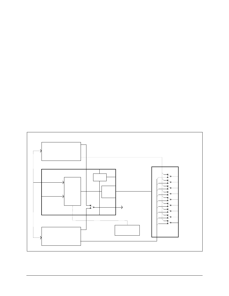
Description (With RS-301 Option)
The 1:1 switch, when used with the RS-301 Remote Switch, is a fully-automated
protection switch designed for use with the Comtech EFData SDM-300/-300A Satellite
Modem that are equipped with the 8-Channel MUX option. It provides redundancy for
the one prime modem using identical backup satellite modem. The 1:1 switch provides
common interfaces for the RF uplink and downlink equipment. The integrated uplink 1:1
switch and downlink splitter operate at IF frequencies in the range of 50 to 180 MHz.
The RS-301 Remote Switch is a separate 19-inch (48.3 cm) rack-mounted chassis. It is
controlled by the 1:1 switch, and provides redundancy for the data interface between the
primary modem, backup modem, and customer equipment. The front panel provides
convenient access to eight tributary data channels (EIA-232 and EIA-422 clock and data)
and one auxiliary data channel. Figure 1-3 illustrates the system block diagram.
Note: The default connections are to Modem A.
1 F O R 1 S W IT C H
M O D E M R E M O T E
E IA -4 8 5
S TAT U S FA U LT S
S D M -3 0 0 / 3 0 0 A
M O D E M A
T R A N S M IT IF
R E C E IV E IF
R E C E IV E IF
B A S E B A N D D ATA
T X /R X
S D M -3 0 0 / 3 0 0 A
M O D E M B
T R A N S M IT IF
J1 0
J6
J1 5
R S -3 0 1
R E M O T E
S W IT C H
J5
J1 3
J1 4
E IA -2 3 2 O R E IA -4 8 5
H O S T T E R M IN A L
O R C O M P U T E R
M O D E M B D ATA (8 T R IB & 1 A U X )
B A S E B A N D D ATA
T X /R X
S W IT C H
M & C
L O G IC
S W IT C H
C O N T R O L
T R A N S M IT IF
5 0 T O 1 8 0 M H z T O
U P C O N V E R T E R
J1
J8
J9
J7
J4
J1 6
J1 4
M O D E M A D ATA (8 T R IB & A U X )
J1 T R IB 1 D ATA
J2 T R IB 2 D ATA
J3 T R IB 3 D ATA
J4 T R IB 4 D ATA
J5 T R IB 5 D ATA
J6 T R IB 6 D ATA
J7 T R IB 7 D ATA
J8 T R IB 8 D ATA
J9 A U X D ATA
R E M O T E
C O N T R O L
N O T E : J7, J8 , A N D J9
A R E N O T U S E D .
S P L IT T E R
C O N T R O L
B U S
E X T E N D E R
C A R D
Figure 1-3. System Block Diagram (With RS-301 Option)