Comtech EF Data SMS-301 User Manual
Page 30
Installation
SMS-301 Redundancy Switch
2–8
Rev. 3
2.3.2.3
Data I/O Connector (J1, J2, J3), 25-Pin (PL/6026)
Note: For EIA-422/-530, EIA-232, V.35, or G.703 applications,
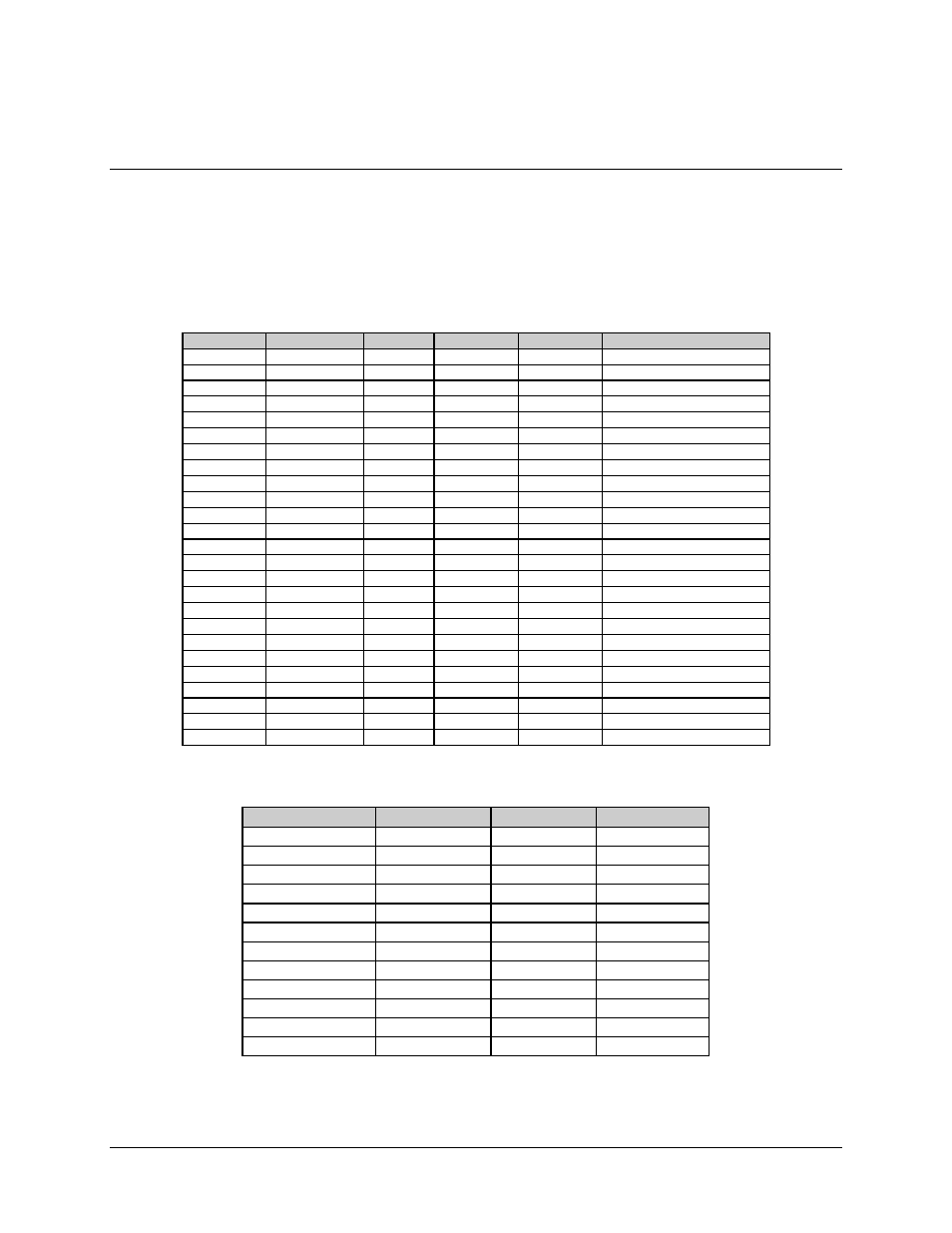
The 25-pin D subminiature connector has the pin assignments shown in Table 2-6.
Table 2-6. Connector Assignments, 25-Pin
Pin #
EIA-422/-530
EIA-232
V.35
G.703
Signal Function
3
RD-A
RXD
RD-A
RD-A
Receive Data
16
RD+B
RD+B
RD+B
2
SD-A
TXD
SD-A
SD-A
Send Data
14
SD+B
SD+B
SD+B
24
TT-A
TXC
SCTE--A
Terminal Timing
11
TT+B
SCTE+B
15
ST-A
ST
SCT-A
Send Timing
12
ST+B
SCT+B
17
RT-A
RXC
SCR-A
Receiver Timing
9
RT-B
SCR-B
4
RS-A
RTS
RTS
Request to Send
19
RS+B
5
CS-A
CTS
CTS
Clear to Send
13
CS+B
8
RR-A
DCD
RLSD
Receiver Ready
10
RR+B
6
DM-A
DSR
DSR
Data Mode
22
DM+B
20
MC-A
MC
MC-A
MC-A
Master Clock (input)
23
MC+B
MC+B
MC+B
18
LL
LL
LL
21
DF
DF
DF
DF
Demod Fault
25
MF
MF
MF
MF
Mod Fault
7
SIGGND
SIGGND
SIGGND
SIGGND
Signal Ground
1
SHLD
SHLD
SHLD
SHLD
The following shows the jumper configurations for EIA-422/530.
EIA-422/-530
V.35
EIA-232
G.703
J6
J6
J19
J5
J7
J7
J23
J10
J8
J8
J24
J11
J9
J9
J25
J12
J14
J14
J27
J13
J15
J15
J28
J14
J17
J16
J29
J18
J18
J18
J30
J20
J20
J20
J17
J21
J21
J21
J22
J22
J22
J26
J26
J26