Comtech EF Data SMS-301 User Manual
Page 107

SMS-301 Redundancy Switch
SDM-2020 System Installation
Rev. 3
C–5
C.1.2.2
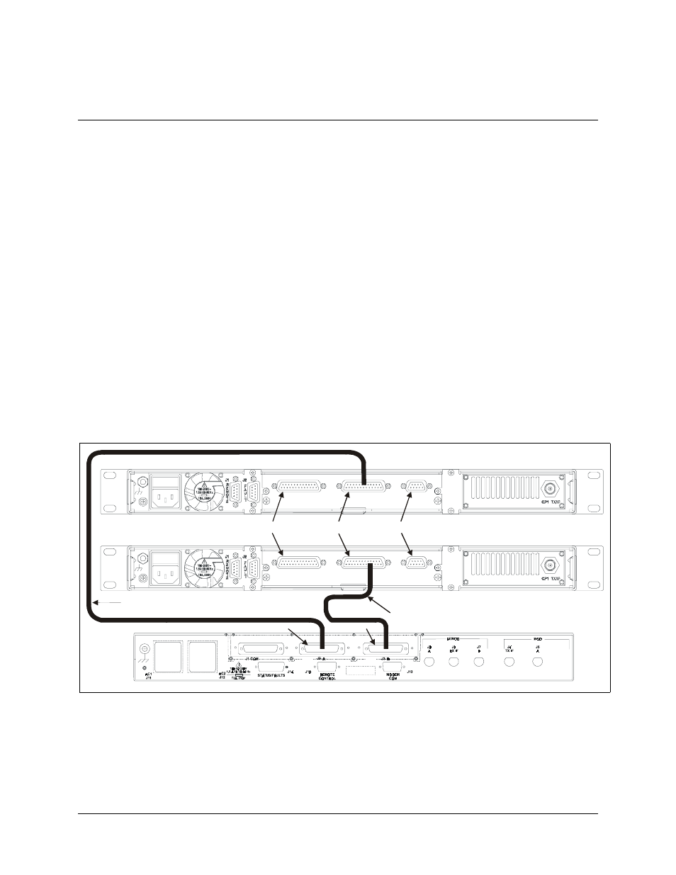
Connect to SDM-2020 Modulator with EIA-422 Interface
Refer to Figure C-2.
1.
Connect the “COMM” data interface connector (J1) to the DTE equipment.
Note: Equivalent cable shall be computer grade, 100
Ω, incorporating twisted and
shielded pairs. Typical length shall be
≤ 16 feet (5 meters).
2.
Connect the “A” data interface connector (J2) to the prime SDM-2020 Modulator
“SERIAL” (J4) connector using Cable (CA/6679) or equivalent.
3. Connect the “B” data interface connector (J3) to the backup SDM-2020
Modulator “SERIAL” (J4) connector using Cable (CA/6679) or equivalent
Connection to SDM-2020 Satellite Modulator with EIA-422 (DVB) TX Interface
(18 Mbit/s Serial Data)
Note: The section defines the requirements of the EIA-422 (DVB) TX data
interface for video and high-speed data applications used with the SDM-2020
Satellite Modulator.
SMS-301 1:1 REDUNDANCY SWITCH
S D M -20 2 0 S AT E L L IT E M O D U L AT O R
SE R IA L
J4
PA R A L L EL
J3
A U X
J5
EIA -530
S D M -20 2 0 S AT E L L IT E M O D U L AT O R
SE R IA L
J4
PA R A L L EL
J3
A U X
J5
EIA -530
(S TA N D A R D C O N F IG U R AT IO N )
J2 (A )
J3 (B )
C A B LE (P L/6679)
C A B LE (P L/6679)
J5
J4
J3
Figure C-2. Connect to SDM-2020 Modulator with EIA-422 Interface
