External connections, 3 external connections, Rear panel (standard configuration) – Comtech EF Data SMS-301 User Manual
Page 25: R s -301
SMS-301 Redundancy Switch
Installation
Rev. 3
2–3
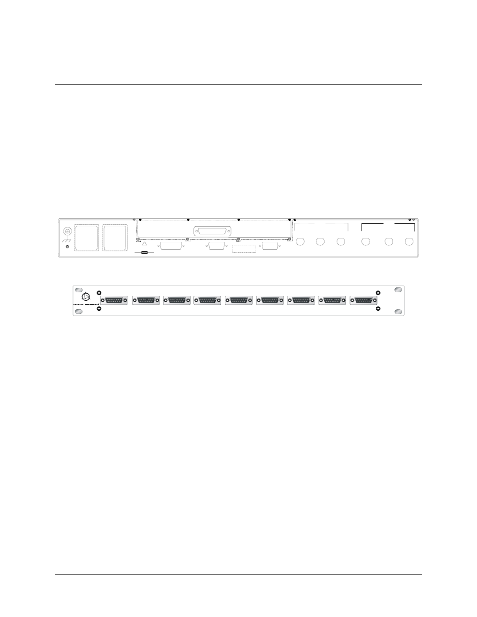
2.3 External
Connections
Connections between the 1:1 switch and other equipment are performed through the rear
panel connectors. These connectors vary depending on whether the Remote Switch (RS-
301) is used.
•
Refer to Table 2-1 for the connector list when the Data I/O is switched internal
to the 1:1 switch.
•
When the 1:1 switch is used with the Remote Switch (RS-301) option, refer to
Table 2-2.
J1 REM O TE SW IT CH CO N TRO L
STAT US/FAULT S
RE MOTE
CON TRO L
J1 4
AC 1
J11
AC2
J1 2
MO D EM
COM
J1 0
J1 3
J9
A
MO D
J8
RX IF
J7
B
J4
TX IF
J5
A
J6
B
!
10 0 TO 240 V
1.5 A 5 0 TO 60 Hz
T2A , 250 V
DE MOD
Rear Panel (Standard Configuration)
TRIB 1 DATA
TRIB 2 DATA
TRIB 3 DATA
TRIB 4 DATA
TRIB 5 DATA
TRIB 6 DATA
TRIB 7 DATA
TRIB 8 DATA
AUX
J9
J8
J7
J4
J1
J2
J3
J5
J6
R S -301
Rear Panel (With RS-301 Option)
Figure 2-1. SMS-301 Rear Panel Configurations
- CDD-880 (124 pages)
- CDM-800 (130 pages)
- ODMR-840 (184 pages)
- CDM-750 (302 pages)
- CDM-840 (244 pages)
- SLM-5650A (420 pages)
- CTOG-250 (236 pages)
- CDM-700 (256 pages)
- CDM-760 (416 pages)
- CDM-710G (246 pages)
- CDM-600/600L (278 pages)
- CDMR-570L (512 pages)
- CDM-625 (684 pages)
- CDM-625A (756 pages)
- CDD-564A (240 pages)
- CDD-564L (254 pages)
- CLO-10 (134 pages)
- MCED-100 (96 pages)
- CDMR-570AL (618 pages)
- CDM-600 LDPC (2 pages)
- BUC Power Supply Ground Cable (2 pages)
- MPP70 Hardware Kit for CDM-570L (4 pages)
- MPP50 Hardware Kit for CDM-570L (4 pages)
- CDM-625 DC-AC Conversion (4 pages)
- CDM-625 DC-AC Conversion with IP Packet Processor (4 pages)
- DMDVR20 LBST Rev 1.1 (117 pages)
- DMD2050E (212 pages)
- DMD-2050 (342 pages)
- DMD1050 (188 pages)
- OM20 (220 pages)
- QAM256 (87 pages)
- DD240XR Rev Е (121 pages)
- MM200 ASI Field (5 pages)
- DM240-DVB (196 pages)
- MM200 (192 pages)
- CRS-150 (78 pages)
- CRS-280L (64 pages)
- CRS-170A (172 pages)
- CRS-180 (136 pages)
- CiM-25/8000 (186 pages)
- CiM-25 (26 pages)
- CRS-500 (218 pages)
- CRS-311 (196 pages)
- CIC-20 LVDS to HSSI (26 pages)