Comtech EF Data SMS-301 User Manual
Page 29
SMS-301 Redundancy Switch
Installation
Rev. 3
2–7
2.3.2.2
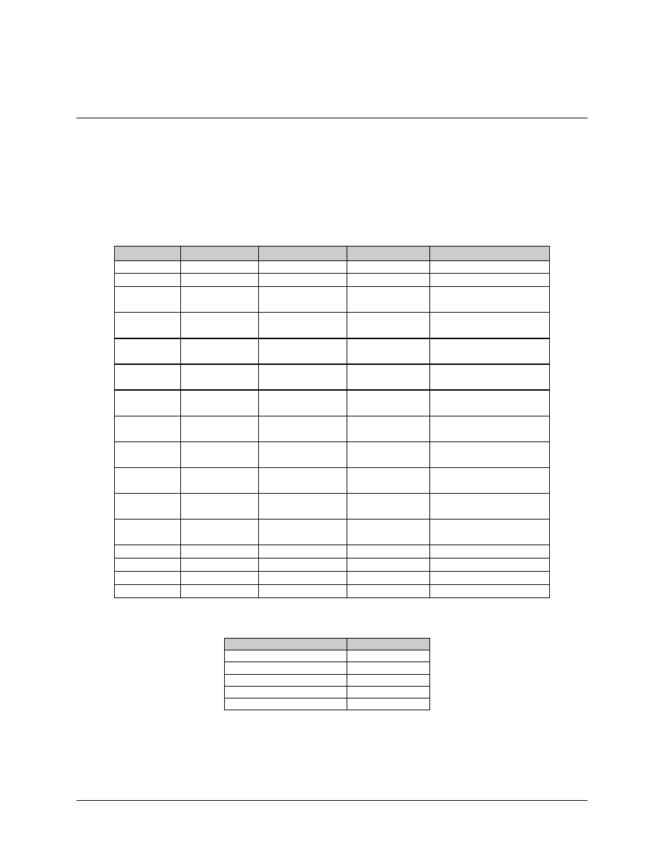
Data I/O Connector (J1, J2, J3), 37-Pin (PL/5952)
Note: For EIA-422/-449, V.35, and G.703 applications.
The 37-pin D subminiature connector pin assignments are shown in Table 2-5.
Table 2-5. Data I/O Connectors, 37-Pin
Pin #
EIA-422/-449
V.35
G.703
Signal Function
1
SG
SG
SG
Signal Ground
3
MF
MF
MF
MOD Fault
4
22
SD-A
SD-B
SD-A
SD-B
SD-A
SD-B
Send Data
5
23
ST-A
ST-B
ST-A
ST-B
Send Timing
6
24
RD-A
RD-B
RD-A
RD-B
RD-A
RD-B
Receive Data
7
25
RS-A
RS-B
RS-A
RS-B
Request to Send
8
26
RT-A
RT-B
RT-A
RT-B
Receiver Timing
9
27
CS-A
CS-B
CS-A
CS-B
Clear to Send
11
29
DM-A
DM-B
DM-A
DM-B
Data Mode
13
31
RR-A
RR-B
RR-A
RR-B
Receiver Ready
17
35
TT-A
TT-B
TT-A
TT-B
Terminal Timing
16
34
MC-A
MC-B
MC-A
MC-B
MC-A
MC-B
Master Clock
(Input)
19
SG
SG
SG
Signal Ground
20
SG
SG
SG
Signal Ground
21
DF
DF
DF
DEMOD Fault
37
SG
SG
SG
Signal Ground
The following shows the jumper configurations for EIA-422/449, V.35, and G.703.
EIA-422/449/V.35
G.703
JP2
JP1
JP3
JP6
JP4
JP7
JP5
JP6
JP9
- CDD-880 (124 pages)
- CDM-800 (130 pages)
- ODMR-840 (184 pages)
- CDM-750 (302 pages)
- CDM-840 (244 pages)
- SLM-5650A (420 pages)
- CTOG-250 (236 pages)
- CDM-700 (256 pages)
- CDM-760 (416 pages)
- CDM-710G (246 pages)
- CDM-600/600L (278 pages)
- CDMR-570L (512 pages)
- CDM-625 (684 pages)
- CDM-625A (756 pages)
- CDD-564A (240 pages)
- CDD-564L (254 pages)
- CLO-10 (134 pages)
- MCED-100 (96 pages)
- CDMR-570AL (618 pages)
- CDM-600 LDPC (2 pages)
- BUC Power Supply Ground Cable (2 pages)
- MPP70 Hardware Kit for CDM-570L (4 pages)
- MPP50 Hardware Kit for CDM-570L (4 pages)
- CDM-625 DC-AC Conversion (4 pages)
- CDM-625 DC-AC Conversion with IP Packet Processor (4 pages)
- DMDVR20 LBST Rev 1.1 (117 pages)
- DMD-2050 (342 pages)
- DMD2050E (212 pages)
- DMD1050 (188 pages)
- OM20 (220 pages)
- QAM256 (87 pages)
- DD240XR Rev Е (121 pages)
- MM200 ASI Field (5 pages)
- DM240-DVB (196 pages)
- MM200 (192 pages)
- CRS-150 (78 pages)
- CRS-280L (64 pages)
- CRS-170A (172 pages)
- CRS-180 (136 pages)
- CiM-25/8000 (186 pages)
- CiM-25 (26 pages)
- CRS-500 (218 pages)
- CRS-311 (196 pages)
- CIC-20 LVDS to HSSI (26 pages)