System installation (standard configuration), B.1.1 system installation (standard configuration) – Comtech EF Data SMS-301 User Manual
Page 96
SDM-300/-300A System Installation
SMS-301 Redundancy Switch
B–2
Rev. 3
B.1.1
System Installation (Standard Configuration)
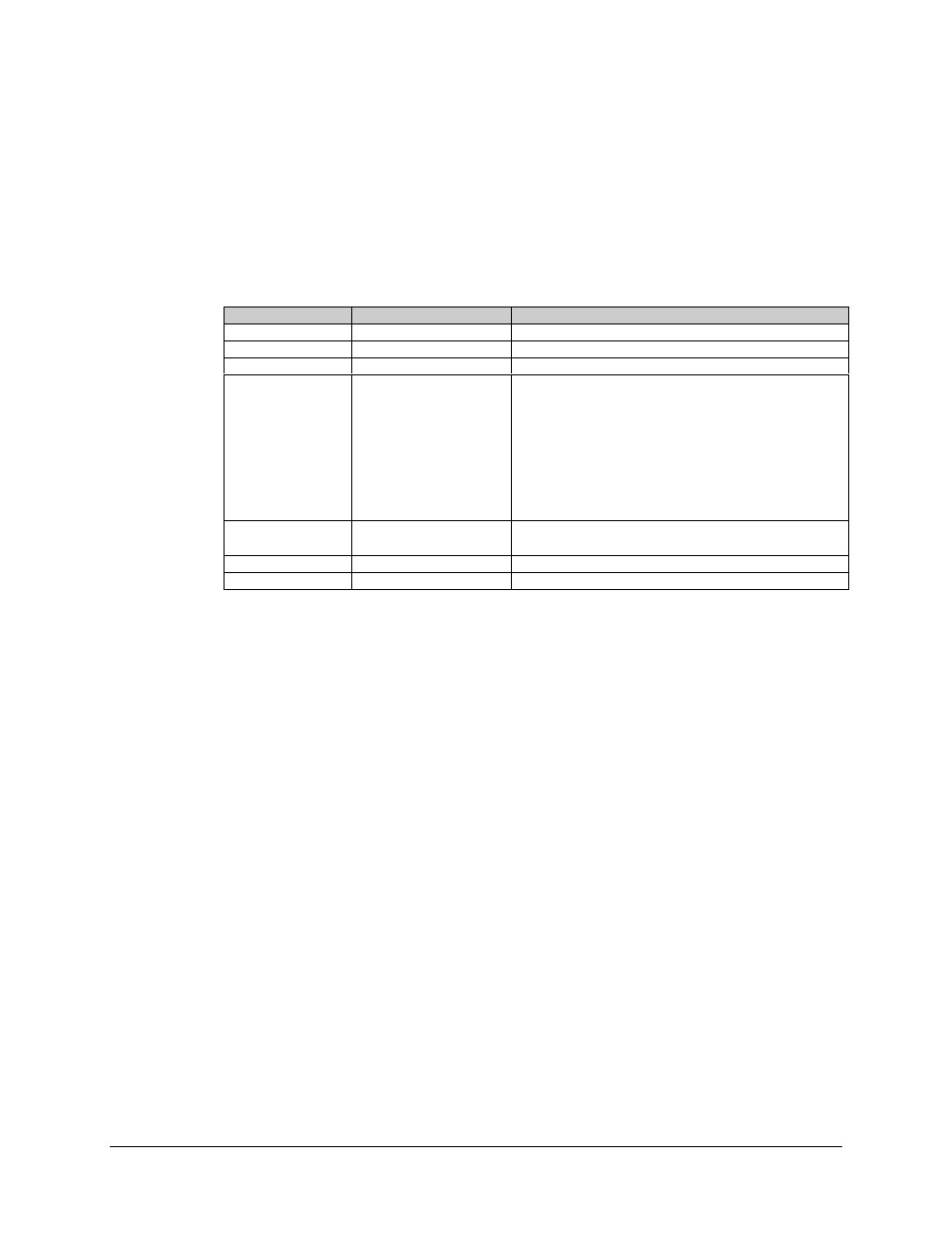
Refer to Table B-1 for cable assemblies applicable to the standard configuration.
Table B-1. Standard Configuration Cabling
Item No.
Part No.
Description
1A
PL/3588
Data Cable, 25-pin
1B
PL/0725
Data Cable, 34-pin
1C
PL/0730
Data Cable, 37-pin
1D
PL/0737-4 (PL/5665-4)
PL/0737-6 (PL/5665-8)
PL/0737-8 (PL/566-12)
Data Cable, 50-pin, 4 feet
Data Cable, 50-pin, 8 feet
Data Cable, 50-pin 8 feet
Notes:
1.
Data Cable, 50-pin is available with right angle
connector, PL/0737R-X.
2.
Data Cable, 50-pion is available with ECL
interface, PL/4807-X.
2
PL/0813-4
PL/0813-8
BNC Cable, 48.0
± 1.5 inches (length)
BNC Cable, 96.0
± 3.0 inches (length)
3
PL/6239
Cable Assy, Remote Control with Termination
4
PL/6051-1
Power Cable Assemblies
Note: Alternate part is provided in parenthesis.
Refer to Figure B-1 for cabling the standard configuration.
1.
Mount the SMS-301 1:1 switch in a standard equipment rack. Secure with four
bolts.
2.
Connect the data interface connector (Figure B-1) as follows:
a.
Connect the “COMM” data interface connector (J1) to the customer-
furnished equipment, using a customer-furnished cable assembly.
b.
Connect the “A” data interface connector (J2) to the prime modulator Data
I/O interface connector, using applicable data cable listed in Table B-1,
items 1A through 1D.
c.
Connect “B” data interface connector (J3) to the backup modulator data I/O
interface connector using applicable data cable listed in Table B-1, items 1A
through 1D.
3. Connect REMOTE connector at the prime modulator, bacvkup modulatotr, to the
COMM connector at the 1:1 switch, using PL/6239 cable assembly. Connect to
customer-furnished equipment.