Comtech EF Data SMS-301 User Manual
Page 109
SMS-301 Redundancy Switch
SDM-2020 System Installation
Rev. 3
C–7
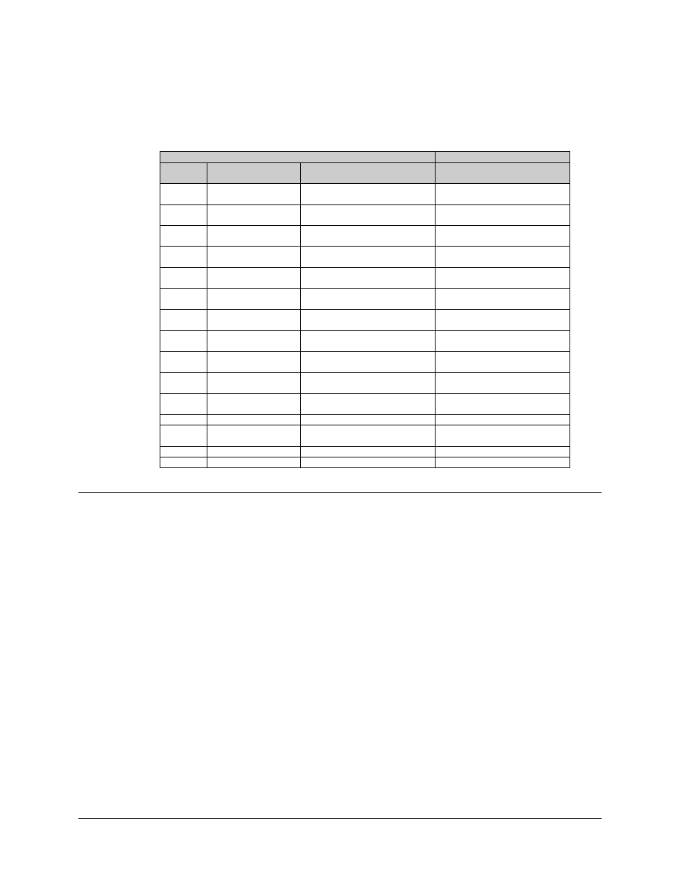
The cable pin assignments are specified in Table C-4.
Table C-4. Cable Pin Assignments (CA/6217)
SMS-301 (DB-37)
SDM-2020M DVB
Pin #
Name
Signal Function
Parallel or Serial
(J3 DB 25 EIA-422)
19
37
CLK-A
CLK-B
Master Clock
(TT Serial)
1
14
34
15
SYNC-A
SYNC-B
Synchronized
12
25
33
14
VAL-A
VAL-B
Data Valid
11
24
32
13
DAT7-A
DAT7-B
Data Bit 7
(Serial Data Bit)
3
16
31
12
DAT6-A
DAT6-B
Data Bit 6
4
17
30
11
DAT5-A
DAT5-B
Data Bit 5
5
18
29
10
DAT4-A
DAT4-B
Data Bit 4
6
19
28
9
DAT3-A
DAT3-B
Data Bit 3
7
20
27
8
DAT2-A
DAT2-B
Data Bit 2
8
21
26
7
DAT1-A
DAT1-B
Data Bit 1
9
22
25
6
DAT0-A
DAT0-B
Data Bit 0
10
23
1
SG
Signal Ground
13
21
2
REFCLK-A
REFCLK-B
Reference Clock
(ST Serial)
15 Reference Clock or
2 Ground
22
DF
DEMOD Fault
AUX (J5) Pin 2 DB 9
3
MF
MOD Fault
AUX (J5) Pin 6 DB 9
C.1.3.2
Connect to SDM-2020 Modulator with EIA-422 DVB TX Interface
Refer to Figure C-3.
1.
Connect the “COMM” data interface connector (J1) to the DTE equipment.
Note: Equivalent cable shall be computer grade, 100
Ω, incorporating twisted and
shielded pairs. Typical length shall be
≤ 16 feet (5 meters).
2.
Connect the “A” data interface connector (J2) to the prime SDM-2020 Modulator
“SERIAL” (J4) connector and “AUX” (J5) connector using Cable (CA/6217) or
equivalent.
3. Connect the “B” data interface connector (J3) to the backup SDM-2020
Modulator “SERIAL” (J4) connector and “AUX” (J5) connector using Cable
(CA/6217) or equivalent