5 cables, 4 initial configuration check, 1 standard factory configuration – Comtech EF Data DMD-2050E User Manual
Page 40
DMD2050E Universal Satellite Modem
Installation
MN-DMD2050E Revision 2
2–4
2.3.5
Cables
To meet EMC directives, make sure to use shielded cables that have the shield terminated to the
conductive backshells. To meet low voltage directives, use cables that have insulation
flammability ratings of 94 VO or better.
CAUTION
Before you install the mating connectors, first make sure to start the unit and set the
Interface Type (MIL-188-114A, G.703, etc.) from the front panel. If you do not set the
Interface Type, there is a risk of damage to the Universal Interface Module.
2.4
Initial Configuration Check
The unit leaves the factory with preset configuration defaults.
IMPORTANT
The transmit and receive interface type settings vary depending on the options ordered
from the factory.
When you first start the unit, do an inspection of the preset configuration. To lock up the unit,
enter ‘IF Loopback Enable’ in the Test Menu, or connect a loopback cable from J1 to J2 on the
rear of the unit.
See also:
Chapter 4. User Interfaces
2.4.1
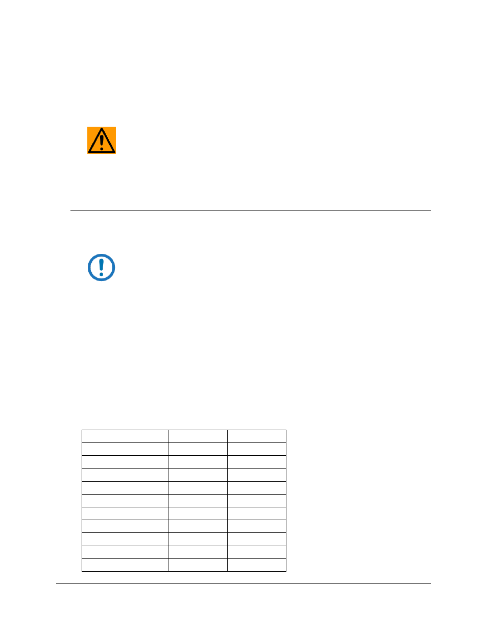
Standard Factory Configuration
Setting
Modulator
Demodulator
Data Rate
2.048 Mbps
2.048 Mbps
Mode
Closed Network Closed Network
Satellite Framing
None
None
Scrambler
V.35 (IESS)
V.35 (IESS)
Drop and Insert
Disabled
Disabled
Inner FEC
1/2 Rate Viterbi 1/2 Rate Viterbi
Outer FEC
Disabled
Disabled
Modulation
QPSK
QPSK
Frequency
70.000000 MHz 70.000000 MHz
Modulator Output Power -20 dBm
N/A