J.1.2 basic setup (example) – Comtech EF Data DMD-2050E User Manual
Page 305
DMD2050E Universal Satellite Modem
ITA Operation
MN-DMD2050E Revision 2
J–3
J.1.2 Basic Setup (Example)
The modems will be initially configured in the lowest modulation and coding rate for the
characteristic of the link. ITA uses a combination or composite data rate (serial + Ethernet) that
will allow selection of any ITA waveforms. This means that all combinations of modulation and
code rate have enough Ethernet bandwidth to achieve proper configuration and that all
modulation and code rates are of the same block size. The setup will cover each of the four
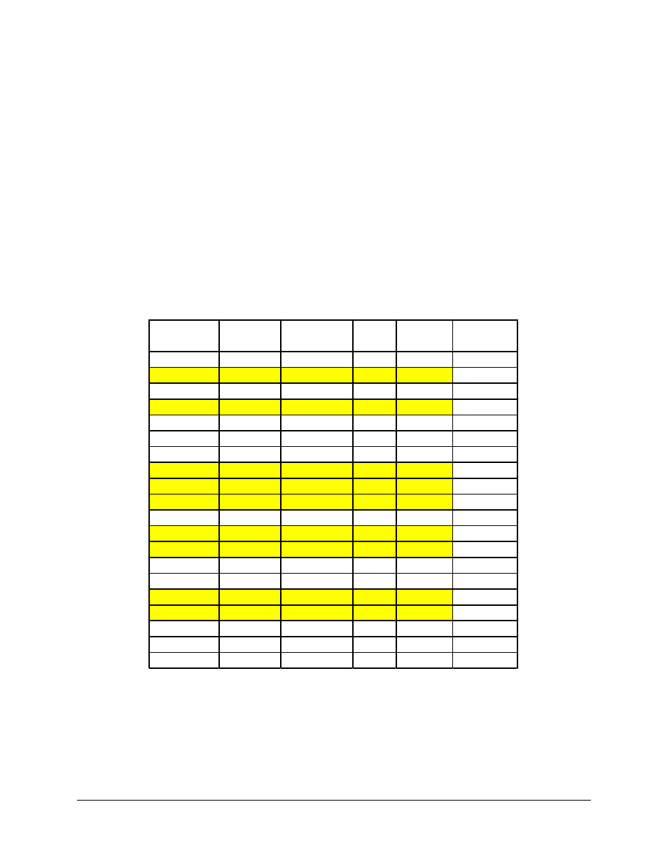
modulations and each of the five code rates by selecting various combinations. Table J-1 is a
rank ordering of modulation and coding rates entered by the operator, by Es/No requirement.
The bits/Symbol provides an indication of the efficiency of the particular combination selected.
The test case ITA waveforms are shown in Table J-1.
Table J-1 - ITA Waveforms and Selection
Modulation Code Rate Bits/Symbol
Typical
Eb/No
Required
Es/No
Selected
Test Cases
16APSK
0.95
3.800
10.25
16.05
*
8PSK
0.95
2.850
9.31
13.86
16APSK
0.875
3.500
8.40
13.84
*
8PSK
0.875
2.650
7.50
11.69
16APSK
0.75
3.000
6.59
11.37
16APSK
0.667
2.667
5.64
9.90
8PSK
0.75
2.250
5.64
9.16
*
QPSK
0.95
1.900
6.18
8.96
8PSK
0.667
2.000
4.70
7.71
QPSK
0.875
1.750
4.81
7.24
16APSK
0.5
2.000
4.01
7.02
*
BPSK
0.95
0.950
6.12
5.90
QPSK
0.75
1.500
3.55
5.31
8PSK
0.5
1.500
3.16
4.92
QPSK
0.667
1.330
2.97
4.22
*
BPSK
0.875
0.875
4.78
4.20
BPSK
0.75
0.750
3.52
2.27
QPSK
0.5
1.000
2.07
2.07
BPSK
0.667
0.667
2.95
1.19
*
BPSK
0.5
0.500
2.06
-0.95
Initial configuration will be the lowest modulation and coding combination. In this example BPSK
Turbo 2/3 Rate. Selecting a serial rate of 2048k and a symbol rate of 640k allows all possible
combinations (except BPSK 1/2) this will be relevant later, to be achieved within a common block
size, so this was selected, shown in Table J-2. The ITA configuration is then entered as shown in
Table J-3, and shown in Figure J-1 through Figure J-6.