4 alarm (j15) – Comtech EF Data DMD-2050E User Manual
Page 158
DMD2050E Universal Satellite Modem
External Connections
MN-DMD2050E Revision 2
5–6
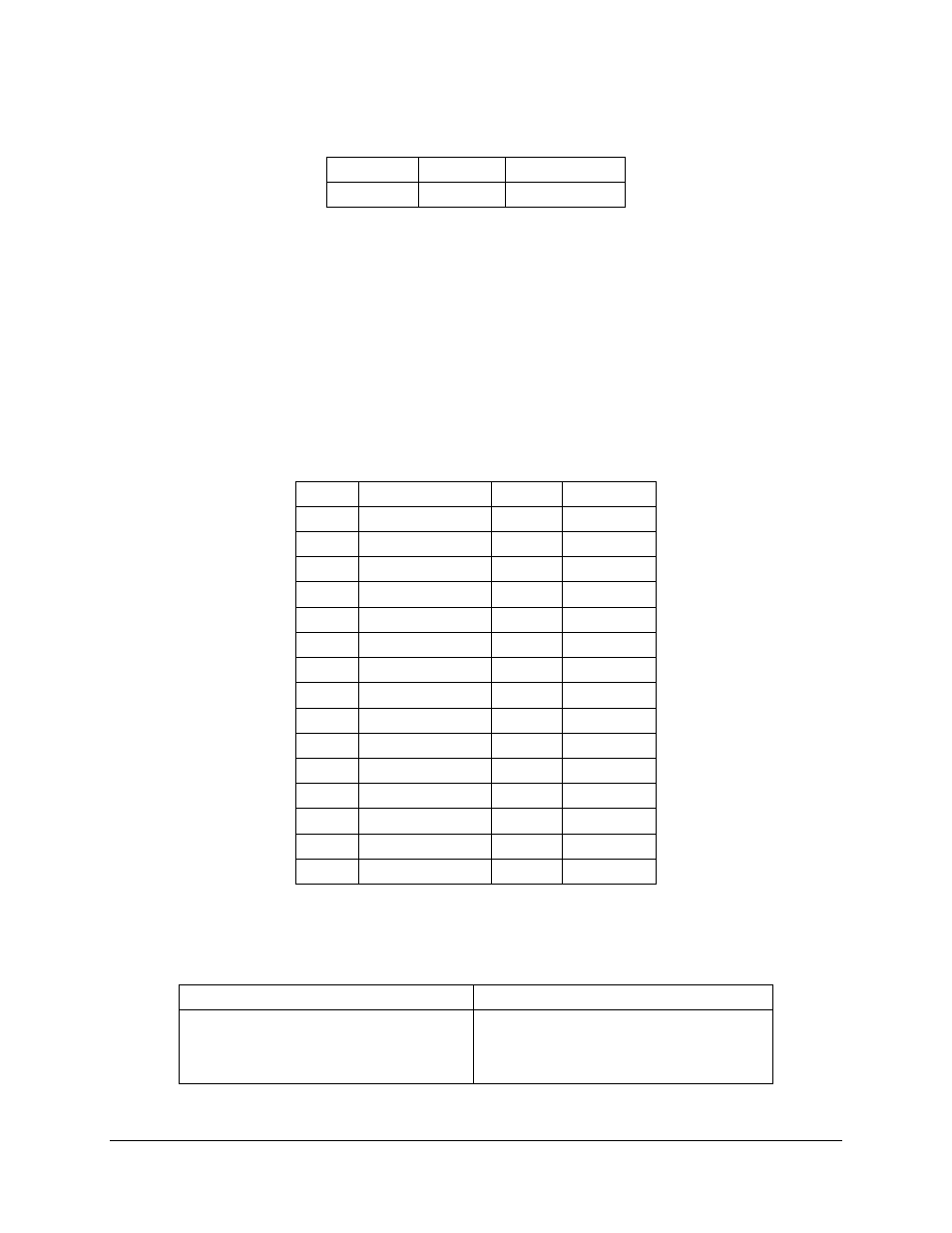
5.3.4 ALARM (J15)
Label
Description Connector Type
ALARM J15 Alarm Port 15-pin Female D
The Alarm port uses contact closures to identify the status of the unit. Pins 1 through 6 supply
Form C contacts for major alarm status on the modulator and demodulator.
Normally Open or Normally Closed conditions indicate a FAULTED or OFF state.
•
C = Closed
•
NO = Normally Open
•
NC = Normally Closed
Table 5-4. Pinouts for J15 ALARM Port 15-pin Female D Connector
Pin No. Signal Name
Signal
Direction
1
Mod Fault - C
MF-C
No Direction
2
Mod Fault – NC
MF-NC
No Direction
3
Mod Fault – NO
MF-NO
No Direction
4
Demod Fault - C
DF-C
No Direction
5
Demod Fault – NC DF-NC
No Direction
6
Demod Fault – NO DF-NO
No Direction
7
Prompt - C
CEF-C
No Direction
8
Prompt – NC
CEF-NC No Direction
9
Prompt – NO
CEF-NO No Direction
10
Service – C
SP1-NO No Direction
11
Service – NC
SP1-NC No Direction
12
Service – NO
SP2-NO No Direction
13
No Connect
SP2-NC No Direction
14
AGC Out
AGC
No Direction
15
Ground
GND
---
Use the front panel to set up Prompt and Service alarm summaries. Select one summary type for
each alarm type:
Prompt Alarms Summaries
Service Alarms Summaries
a) Prompt alarms
b) Prompt and Tx Minor alarms
c) Prompt and Tx minor and Tx Major alarms
a) Service alarms
b) Service and Rx Minor alarms
c) Service and Rx minor and Rx Major alarms