AMETEK MX CTSL User Manual
Page 85
User Manual
MX-CTSL Compliance Test System
California Instruments
Revision J
85
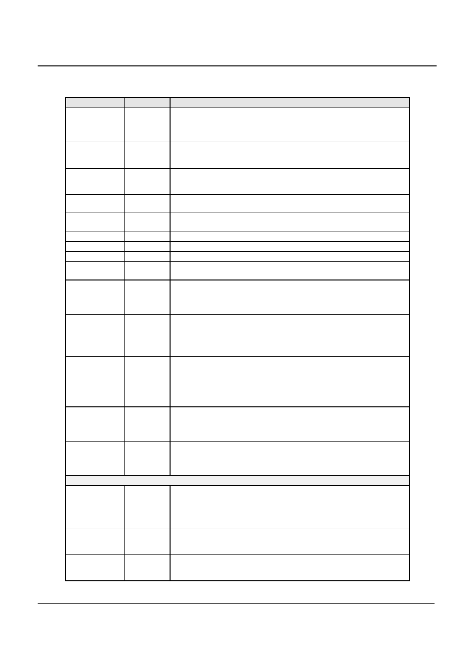
Field / Control
Location
Description
Power
button
Upper left
corner
Click on Power to toggle the power source output voltage, unless power
source is already programmed to 230V. The Flicker module can be
configured to turn off the power after every test, in that case therefore, the
user will have to click Power On before starting the test.
Start button
Upper left
corner
Starts the flicker test using presently selected parameters. Once a test is
running, parameter cannot be changed. Starting a test also causes data to
be written to the test data file.
Stop button
Upper left
corner
Stop the acquisition process. The Stop button can be used to abort a test
prematurely. The data files will be closed and will only contain data up to
the point at which the test was aborted.
Report Button
Upper left
corner
Used to produce a test report in WORD. A WORD must be installed to
generate the report.
Power Button
Upper left
corner
Can manually toggle the power on/off. A PC to power source
communication is needed before it is enabled.
Frequency
Left Panel
Displays signal frequency
V-rms (volt)
Left Panel
Displays Voltage rms value
Test Start Time
Left panel
This field always shows the start time of the test in progress. The test
duration is shown in the bottom panel.
Highest d
c
%
Left panel
Displays the highest Relative Steady State voltage change (d
c
) in % found
so far during the test. This represents the difference between two adjacent
steady-state voltages relative to the nominal voltage. The standard
requires that d
c
must be less than or equal to 3 % for the EUT to PASS.
Highest d
max
%
Left panel
Displays the highest Maximum relative voltage change (d
max
) in %. found
so far during the test. This represents the difference between the maximum
and minimum rms values of the voltage change characteristic relative to the
nominal voltage. The standard requires that d
max
must be less than or equal
to 4 % for the EUT to PASS.
Highest d
t
%
Left panel
Displays the highest Relative voltage change characteristic (d
t
). This value
represents the change in rms voltage, relative to the nominal voltage, as a
function of time and between periods when the voltage is a steady state
condition for at least 1 second. The standard requires that d
t
must be less
than 3 % for the EUT to PASS, although it is permitted to be between 3
and 4 % for less than 200 msec.
Highest Psti
Left panel
Displays the highest Short Term Flicker value found so far during the test.
Each Short Term Flicker severity is evaluated over period of 10 minutes.
The threshold of irritability is Pst = 1 and this value is used as the
PASS/FAIL limit.
Highest Plt
Left panel
Displays the highest Long Term Flicker value (Plt) found so far during the
test. The Plt period is 120 minutes and is calculated using successive Psti
values. The threshold of irritability for long term flicker is 0.65 and this
value is used as the PASS/FAIL limit.
Test Status
Center
panel
This field provides a visual indication of the test result. A Green field with
Pass indicates the EUT passes the Flicker test, a Red field with Fail
indicates the EUT causes too much flicker. Note that the condition of this
field is affected by the user selected test margin. To use the actual IEC test
limits, the test margin should be set to 100 %.
Voltage - rms
(Ut)
Center
panel
Displays the Root Mean Square voltage of the AC source output for each
acquisition window. Acquisition windows are 10 ms for 50 Hz EUT’s and 8
ms for 60 Hz EUT’s.
d
max
%
Center
panel
Displays the present Maximum relative voltage change (d
max
) in %. This
represents the difference between the maximum and minimum rms values
of the voltage change characteristic relative to the nominal voltage. The