Equipment under test pacs 3 - rear panel view – AMETEK MX CTSL User Manual
Page 45
User Manual
MX-CTSL Compliance Test System
California Instruments
Revision J
45
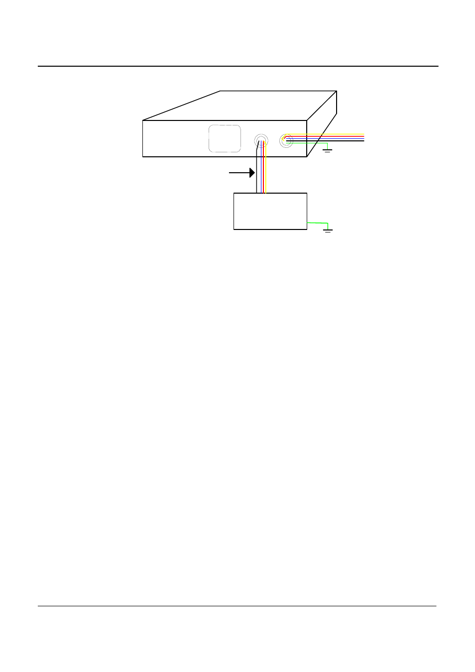
Figure 3-9: EUT Connection distance and wire gauge.
3.6.3
Front Panel Connections and Controls
A DB37 PC Interface Connector is located on the front panel. This connector is in parallel with the rear
panel connector. Either one can be used to connect to the A/D card in the PC. Use front panel interface
connector if rear panel access is difficult.
The “ON “ LED indicates The PACS-3-75 module is powered up. Note: Even if the PACS-3-75 unit is
powered down, the AC input terminals may still be live if the applied source has not been shut down.
The front panel power switch located on the left-hand side of the PACS-3-75 unit energizes the
measurement circuits.
3.6.4
PACS-3-75 AC Input Supply
The AC input to the PACS-3-75 unit is on the right side of the rear panel. The molded cord plugs into the
combination range change/ fuse holder assembly.
The AC power input module has a red plastic fuse holder that also serves as the input voltage range
selecting device. The selected voltage range (115V or 230V) is displayed through a small rectangular
window.
To change the fuse:
To change input range:
1. Remove power cord from input module.
2. Pry cover loose with a small screwdriver.
3. Pull out fuse holder, prying with a screwdriver will be necessary.
4. Replace ½ A fuse and reassemble in reverse order.
1. Remove power cord from input module.
2. Pry cover loose with a small screwdriver.
3. Pull out fuse holder, prying with a screwdriver will be necessary.
Equipment
Under Test
PACS 3 - Rear Panel View
AC OUT AC IN
To AC Source
or OMNI Load
Connection
Keep Wire Length
short. (< 5 ft)
Use proper wire
gauge
Neutral
Phases
A,B,C