AMETEK MX CTSL User Manual
Page 141
User Manual
MX-CTSL Compliance Test System
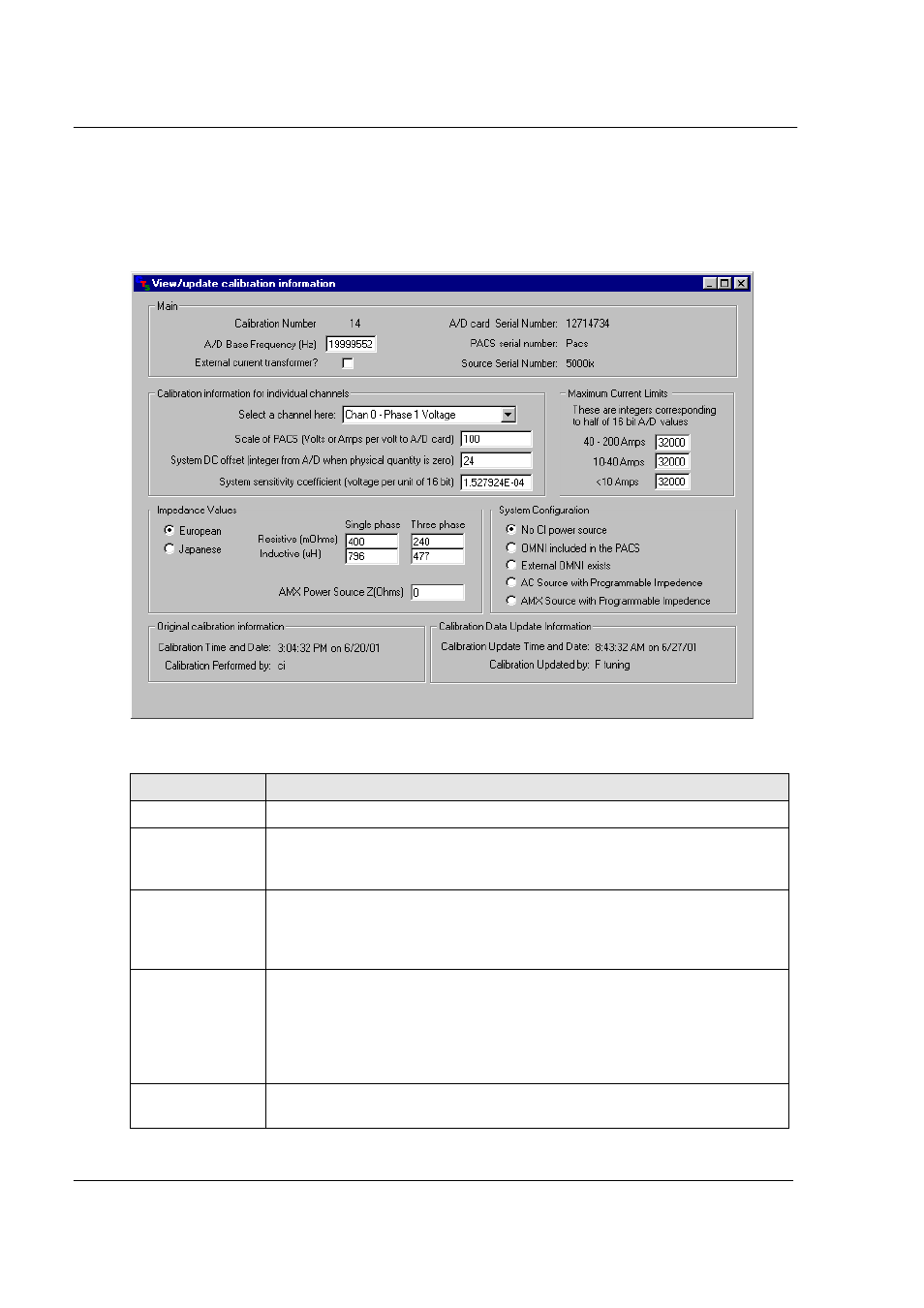
16.2.1 Calibration and Configuration Data
The following calibration and configuration data is available to the user. If the correct password
has been entered, this information can be updated. If not, it can only be viewed. Any changes will
be logged and time stamped so an audit trail is available.
Field
Description
Main
Displays information on the A/D card and base sampling frequency.
Calibration
information
Individual voltage and current channels have calibration coefficients, which
are calculated automatically when running the Calibration module. (See
section 0) Normally, there is no need to edit these values.
Maximum
Current Limits
The CTS system uses three current ranges for maximum resolution and
accuracy of current harmonics measurements. The range coefficients are
used to set the cross over points of these current ranges. These values
should not be change by the user.
Impedance
These fields set the flicker reference impedance values. Values used may
differ between European and Japanese standards. The Japanese standard
presently requires the use of the reference impedance for both harmonics
and flicker tests. During harmonics tests, this will result in high voltage
distortion. This conflict has not been resolved at this time. The impedance
values are different for single and three phase modes.
System
Configuration
This setting determines if reference impedance is used and if so, which
type. Available choices are:
California Instruments
Revision H
138