AMETEK MX CTSL User Manual
Page 58
User Manual
MX-CTSL Compliance Test System
California Instruments
Revision J
58
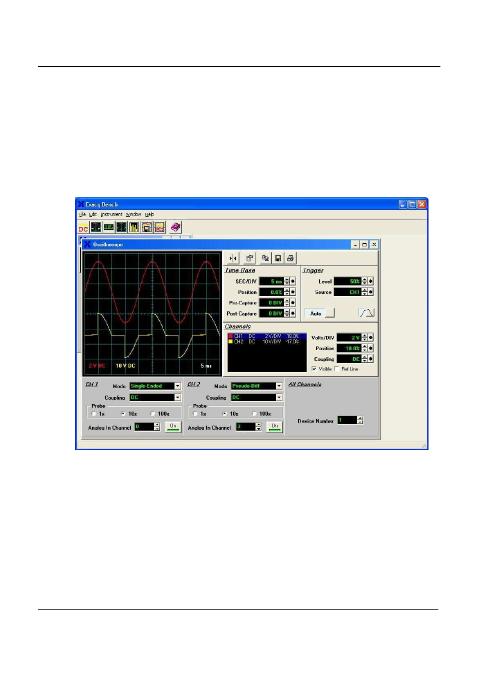
Of course, you may also use the oscilloscope function of the Exacq Bench to display the time domain
signals. Refer to the appropriate section of this manual to identify all the signals and channel numbers, but
for this example, channel 0 is for voltage, and channels 1,2,3 are the (parallel) three current signals. In the
figure below, channel 0 and 3 are displayed (channel 3 is the most sensitive current channel). The CTS
power source was set to 230 Volt – 50 Hz, and a resistive load with a dimmer set to approximately 90
degrees firing angle was applied. The (yellow) current signal was 2.0 Amp rms and the (red) voltage was
230 Volt. The settings for the scope channels and time base function were adjusted to obtain the display as
shown in the figure.
Upon completion of the above tests, you may proceed with installing the CTS software modules that were
supplied with your system.
Figure 3-16: Exacq Scope Test Panel
3.8.5
CTS / GPIB Software Setting Conflict. (For NI PCI-6034E Card Users only)
Each time the CTS is run, a function is called to initialize the A/D card. This call, "Init_DA_brds", actually
does more than A/D initialization. It also sends some commands to the instrument with GPIB address #1
when using a NI GPIB controller. The AC source if used over the IEEE-488 bus is factory set to address 1.
This may cause a problem unless the IEEE-488 address on the power source is changed to an address
other than 1.
The address can be left at 1 on the power source if needed by changing the visaconf.ini file. This file is
typically residing in "c\vxipnp\win95\nivisa" directory. (If not located in this directory, use the Windows
Explorer Find function to locate this file.) This file is not distributed with the CTS software. It is installed
when the National Instruments GPIB software is installed. There is a line under [GPIB-VXI-CONFIG]:
DisableAutoFind=0. The 0 needs to be changed to 1.