AMETEK MX CTSL User Manual
Page 76
User Manual
MX-CTSL Compliance Test System
California Instruments
Revision J
76
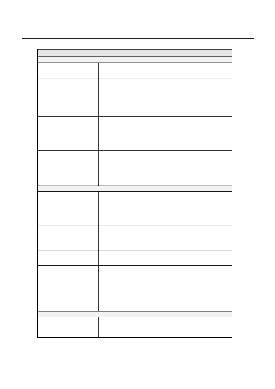
Field / Control
Location
Description
Test Number
Bottom Left
Each test run is assigned a sequential test number. The number for the
current test is displayed in this field. This allows individual test results to
be tracked.
Test Result
Bottom Left
This field provides a visual indication of the test result. A Green field
with Pass indicates the EUT current harmonics are below the limit, a
Red field with Fail indicates the EUT current harmonics are above the
limit. Note that the condition of this field is affected by the user selected
test margin. To use the actual IEC test limits, the test margin should be
set to 100 %. This field depends on the “Window results” of all the
windows up to this test time and if any “Window result” is failed during a
test, Test result will be “Fail”. In other words, this field is “Fail” latching.
Source
Qualification
Bottom Left
This field displays overall AC Source voltage distortion status for the
test so far. At the end of the test, this field indicates if the AC Source
failed the voltage distortion test at any time during the test.
The VTHD indication is given to notify the user of a possible problem
with the AC source voltage distortion, which may invalidate the test
results. The test will not be aborted however if the voltage distortion is
too high.
Start Time
Bottom Left
This field always shows the start time of the test in progress. The test
duration is shown in the bottom panel. See also the “% of test
completed” indication and the progress bar below the Start Time field.
% of test
completed
Left panel
During test execution, this field displays the percentage of the test that
has been completed. Once this number reaches 100 %, the test will
terminate normally. If the user clicks on the Stop button instead, it will
display the point at which the test was aborted.
Test Margin
Bottom
The test margin can be set by the user if a pre-compliance test is
needed and the user wants to set more stringent limits. The test margin
number defaults to 100 % to use the exact IEC limits. A lower
percentage will means the EUT has to pass lower test limits (more
stringent). The value of this field ranges from 50 % to 150 %.
Note that the limit lines in the Graph always display the 100 % IEC
limits. The test margin is only used for Pass or Fail determination.
Test Duration
Bottom
The test duration is the total test time selected by the user. This value
can be set from 0 to 1440 minutes (24 hours). This value should be set
before starting the test as it cannot be changed while a test is in
progress. If the duration is 0 minutes, then only one window will be
acquired.
EUT
Bottom
This field can be used to enter information about the unit under test.
The EUT field contents will be included in the test data file and in any
reports that are printed.
Comments
Bottom
This field can be used to enter any information about the test. The
Comments field contents will be included in the test data file and in any
reports that are printed.
Tested by
Bottom
This field can be used to enter information about the operator. The
“Tested by” field contents will be included in the test data file and in any
reports that are printed.
Customer
This field can be used to enter information on a customer if you are
running tests for a third party. The “Customer” field contents will be
included in the test data file and in any reports that are printed.
Voltage and
Current Graph
Top right
panel
This graph displays the AC voltage and current waveforms. At all times,
two periods of the AC signal are displayed. The voltage is shown in
yellow, the current in green. For Class D tests, the special wave shape
template is displayed in the same graph using red. The percentage of