AMETEK MX CTSL User Manual
Page 138
User Manual
MX-CTSL Compliance Test System
15.6
Flicker Reference Impedances
Flicker measurements require the use of a reference impedance according to IEC 725. Since this
reference impedance has to be matched to the output of the AC source used, a reference
impedance matched to the MX must be used.
For MXCTSL systems, the OMNI-3-37MX is required. For MXCTSL systems, the OMNI-3-37MX is
recommended. For MXCTSHL systems, both OMNI's may be used although only one can be
controlled from the CTSMXH or CTSMXL software while the other must be operated in manual
mode from it’s front panel.
Note that if only an OMNI-3-75 is present in a system running the CTSMXL software, the MX30 or
MX45 programmable impedance must be manually set during flicker testing to adjust the test
impedance for IEC 61000-3-3 flicker testing. This can be done from the MX front panel before the
START button is pressed. Only the resistive portion needs to be adjusted.
Refer to the MX-CTSH User Manual (P/N 7003-972) for OMNI-3-75 specifications.
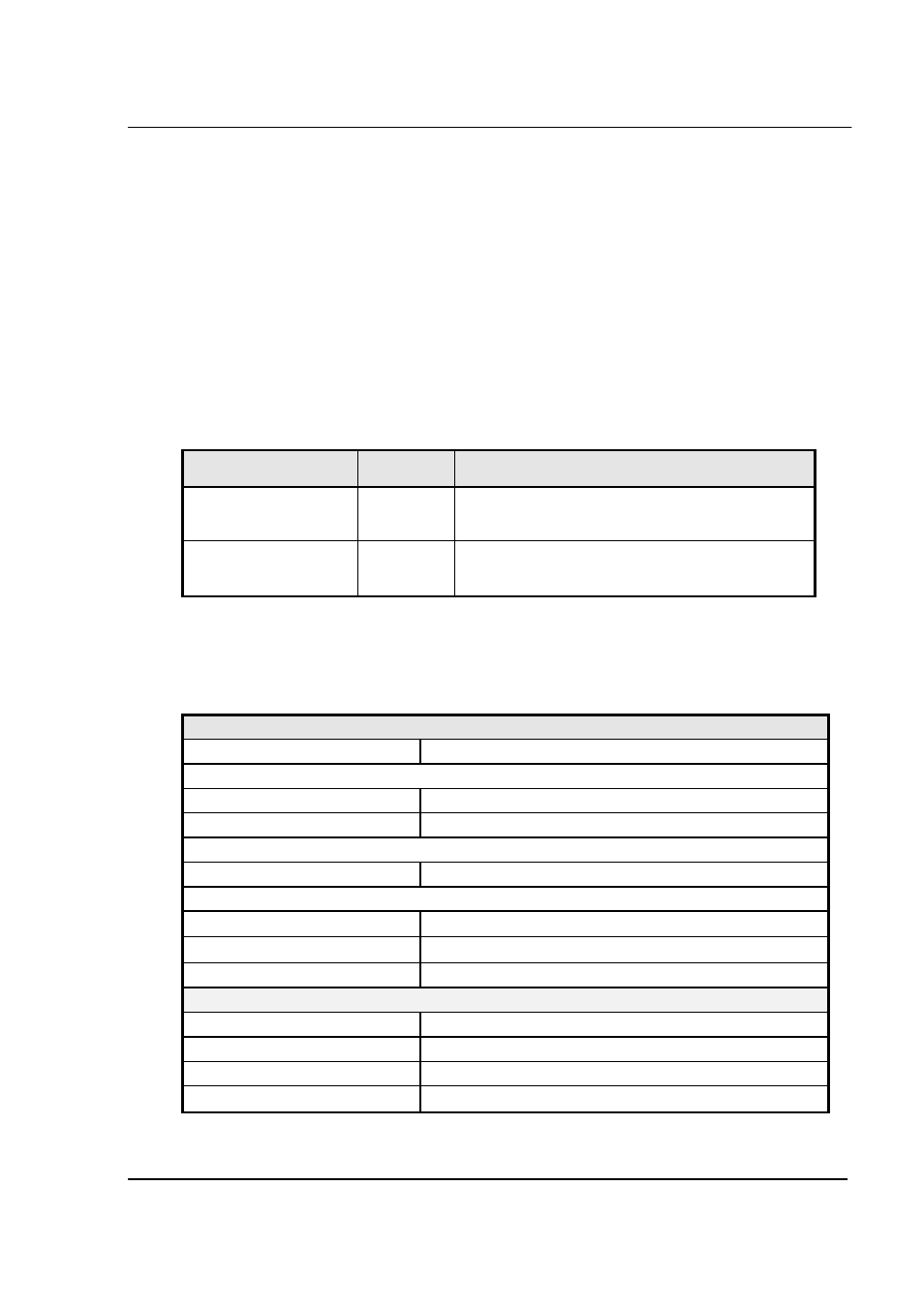
Model
Phases
Flicker Impedance
OMNI-3-37MX
3
0.24 + 0.15j Phase
0.16 + 0.10j Neutral
OMNI-3-75
3
0.15 + 0.15j Phase
0.10 + 0.10j Neutral
15.7
OMNI-3-37MX Specifications
The MXCTS systems based on the MX Series and require the use of an external reference
impedance. The OMNI-3-37MX is not directly controlled by the CTSMXL Software as this capability
is reserved for the OMNI-3-75. To switch the OMNI-3-37MX from bypass to flicker depending on
what test is being run, use the front panel control button.
Reference Impedance
Phases
3
Flicker Mode:
Max. Current
37 A
Useable range
2.0 – 37 A
Bypass Mode:
Max. Current
75.0 A
Impedance @ 50 Hz in Flicker Mode:
Phase
0.24 + j0.15
Ω
Neutral
0.16 + j0.10
Ω
Accuracy
< 5 %
Controls and Indicators
Flicker On/Off push button
Power Led
Bypass mode Led
Flicker mode Led
California Instruments
Revision H
135