AMETEK MX CTSL User Manual
Page 117
User Manual
MX-CTSL Compliance Test System
California Instruments
Revision H
114
11.3
Equipment Classifications
In Annex B of the standard, the EUT operating environment classifications are defined based on IEC
61000-2-4. The classifications are as follows:
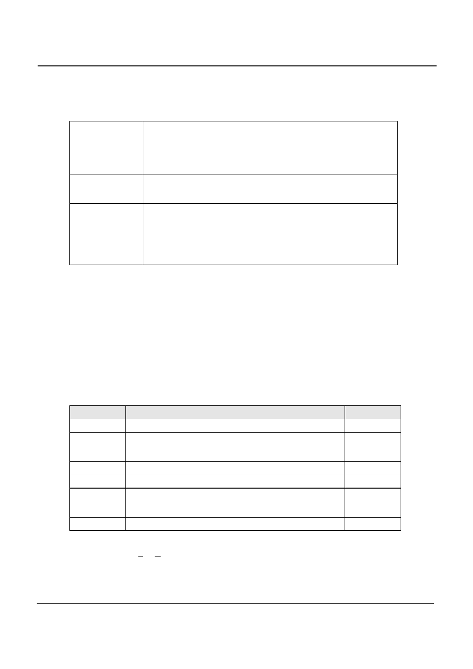
Class 1
Applies to protected supplies with compatibility levels lower than public network
levels. It relates to the use of equipment, which is very sensitive to disturbances
in the power supply, for instance the instrumentation of technological
laboratories, some automation and protection equipment, some computers etc.
This equipment is normally supplied by protected supplies such as
uninterruptible power supplies, filers or surge suppressors.
Class 2
Applies to points of common coupling (PCCs for consumer systems) and in-
plant points of common coupling (IPCs) in the industrial environment in general.
The compatibility levels in this class are identical to those of public networks.
Class 3
Applies only to IPCs in industrial environments. It has higher compatibility levels
than those of class 2 for some disturbance phenomena. This class should be
considered when any of the following conditions are met:
- a major part of the load is fed through converters
- welding machines are present
- large motors are frequently started
- loads vary rapidly
Testing is not recommended for Class 1 equipment. Test level X specifications are to be agreed upon by
the manufacturer and user. Test Levels for environmental Class 2 and 3 equipment are defined by the
generic standard. A user class X (user) with test level equal or higher than those of level 2 may be set as
well.
11.4
Test Levels
The test sequence implemented by this test consists of a series of voltage and phase unbalance variations
consistent with commonly found phenomena on the public utility power grid. The objective of this test is to
evaluate a product for immunity from such variations.
Voltage unbalances are applied at different levels for different product categories. The user must determine
the product class and select the appropriate test level. During the test run, voltage and phase changes are
applied. The voltage levels and phase shifts are determined by the values set in the data entry grid. The
various columns in the test data setup are as follows:
Parameter
Description
Range
Test #
Number of the test. There are three possible tests, 1, 2 and 3.
Fixed
Output
Indicates phase voltage for which level and phase is to be applied.
For each test number, the test will be repeated three time using the
following phase rotations: ABC, BCA, CAB
Fixed
% of Unom
Indicates voltage level to change to in % of nominal voltage.
50 to 150
Angle
Phase angle to shift to for each test number and phase in degrees.
0 to 360
Ku2
Unbalance factor. This value is shown for reference only and is
based on the test levels and phase shifts. It is not directly used to
program the AC source.
Time (s)
Time in seconds to hold the unbalance condition
0.0 to 9999
These parameters can be entered on screen by the operator or loaded from disk. To load a new test or
test class, select the File, Open menu. The default location for IEC test files is:
C:\Program Files\California Instruments\MXGUI\IEC_Test. The following four EN 61000-4-27 test files are
distributed with the MXGUI program: