Clock signals, Reset, Clock signals -8 – Altera Arria 10 Avalon-MM User Manual
Page 55: Reset -8
Clock Signals
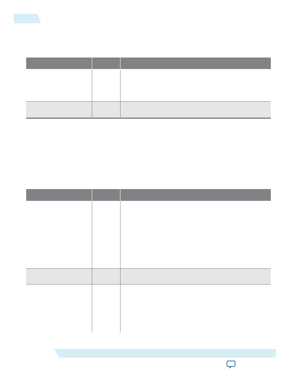
Table 5-4: Clock Signals
Signal
Direction
Description
refclk
Input
Reference clock for the IP core. It must have the frequency
specified under the System Settings heading in the parameter
editor. This is a dedicated free running input clock to the
dedicated
REFCLK
pin.
coreclkout_hip
Output
This is a fixed frequency clock used by the Data Link and
Transaction Layers.
Related Information
on page 7-4
Reset
Refer to Reset and Clocks for more information about the reset sequence and a block diagram of the reset
logic.
Table 5-5: Reset Signals
Signal
Direction
Description
npor
Input
Active low reset signal. In the Altera hardware example designs,
npor
is the
OR
of
pin_perst
and
local_rstn
coming from the
software Application Layer. If you do not drive a soft reset signal
from the Application Layer, this signal must be derived from
pin_perst
. You cannot disable this signal. Resets the entire IP
Core and transceiver. Asynchronous.
This signal is edge, not level sensitive; consequently, you cannot
use a low value on this signal to hold custom logic in reset. For
more information about the reset controller, refer to Reset.
nreset_status
Output
Active low reset signal. It is derived from
npor
or
pin_perstn
.
You can use this signal to reset the Application Layer.
pin_perst
Input
Active low reset from the PCIe reset pin of the device.
pin_perst
resets the datapath and control registers. Configuration via
Protocol (CvP) requires this signal. For more information about
CvP refer to Configuration via Protocol (CvP).
Arria 10 devices can have up to 4 instances of the Hard IP for
PCI Express. Each instance has its own
pin_perst
signal. You
5-8
Clock Signals
UG-01145_avmm
2015.05.14
Altera Corporation
64- or 128-Bit Avalon-MM Interface to the Application Layer