Project 132 current limiters in parallel, Project 131 current limiters – Elenco Snap Circuits Motion User Manual
Page 66
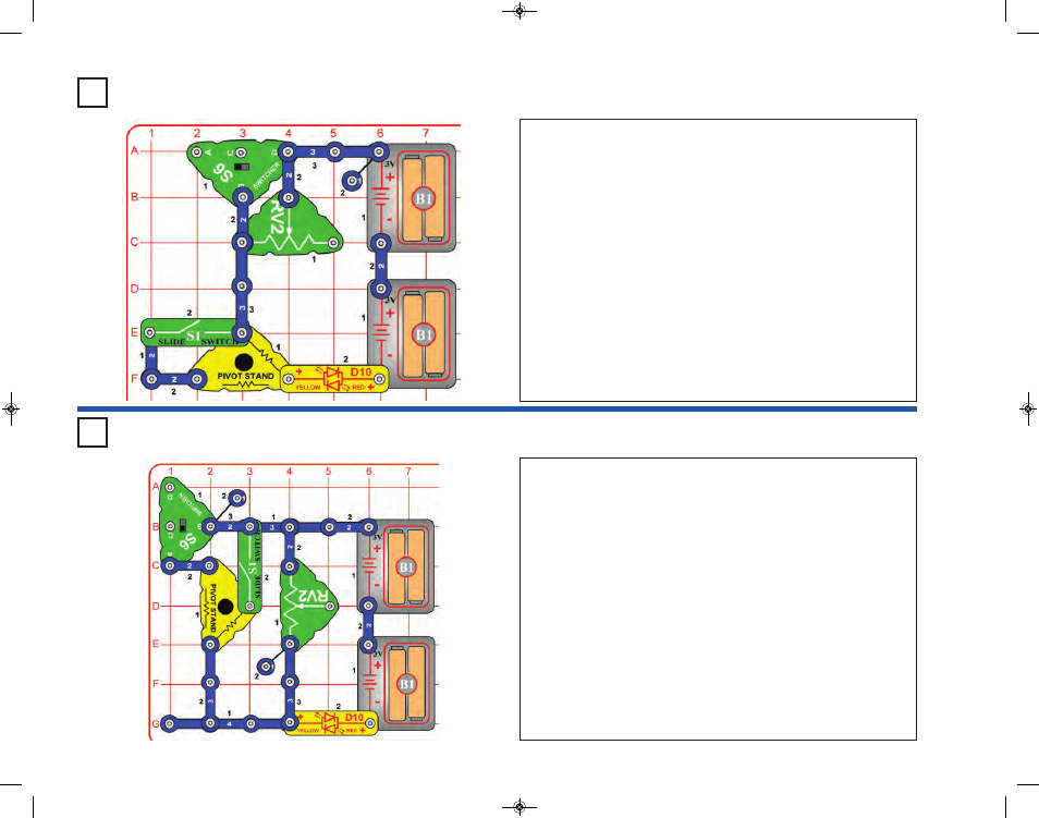
Project 132
Current Limiters in Parallel
Build the circuit, turn off the slide switch (S1) and set the switcher (S6)
to the middle position. The red/yellow bicolor LED (D10) is on dimly.
The LED is not very bright because the only electrical path from the batteries
to the LED is through a 10,000 ohm resistor (the adjustable resistor, which
is used here as a fixed 10,000 resistor, and cannot be adjusted).
Now turn on S1. The LED is a little brighter.
S1 connects a 10,000 ohm resistor in the pivot stand in parallel with
RV2 (fixed at 10,000 ohms here). This gives two 10,000 ohm paths
from the batteries to the LED, instead of just one, so the current is higher
and the LED is brighter.
Now set S6 to the bottom position. The LED is much brighter now.
S6 connects a 47 ohm resistor in the pivot stand in parallel with the two
10,000 ohm resistors already in the circuit (one in the pivot stand and
one in RV2). This adds a much lower 47 ohm path between the batteries
and the LED, so a lot more current flows, and the LED is much brighter.
This circuit does not have an on/off switch, so disconnect it or remove
the batteries when you are finished.
Project 131
Current Limiters
Build the circuit, turn off the slide switch (S1) and set the switcher (S6)
to the middle position. The red/yellow bicolor LED (D10) is on, and you
can use the adjustable resistor (RV2) to vary its brightness a little.
The LED is not very bright because the circuit has two resistors limiting
the electric current through it (a 10,000 ohm resistor in the pivot stand
and RV2, which is adjustable between 200 ohms and 10,000 ohms).
Now turn on S1. The LED is brighter, and RV2 can vary the brightness
more than before.
S1 connects a much smaller 47 ohm resistor (also in the pivot stand) in
parallel with the 10,000 ohm resistor in the pivot stand. The smaller
resistor does not limit the current flow as much as the larger one, so
the LED is brighter.
Now set S6 to the right position. The LED is even brighter now, and RV2
no longer changes the brightness.
S6 bypasses RV2, allowing more current to flow, and making the LED brighter.
This circuit does not have an on/off switch, so disconnect it or remove
the batteries when you are finished.
-65-
SCM-165_Manual_061114.qxp_Layout 1 7/7/14 11:29 AM Page 66