Project 58 more pulleys, Project 57, Project 59 trip-wire lights – Elenco Snap Circuits Motion User Manual
Page 39: Secure pulley
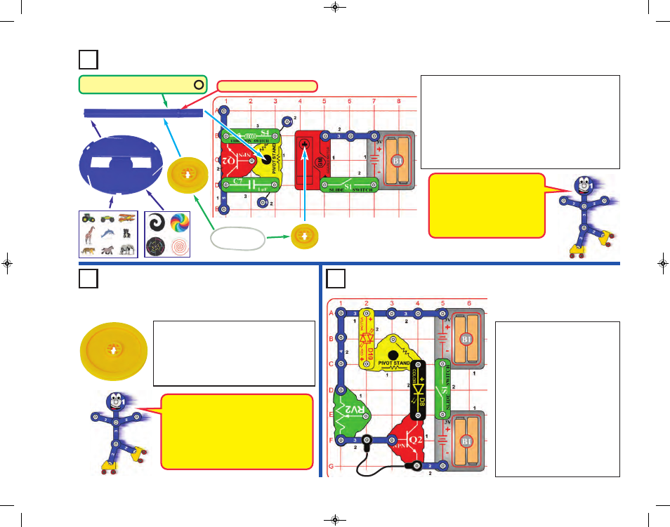
Project 58
More Pulleys
Repeat projects 56/57, but replace each of
the pulleys with the larger 2.1” pulley. Try
this both with the 2.1” pulley on the pivot
stand, and then with it in the geared motor.
Also try it with your own rubber band, as
described in Part E of project 48.
Project 57
In the preceding project, tension in the rubber band
pulls on the “+” shaped bar and pivot stand, and may
pull the pivot stand snaps off the base grid. If so, modify
the circuit to be the one shown here, which uses
additional parts (S4, Q2, and C7) to help hold and
secure the pivot stand in place. In part E, when
repositioning the pivot stand to use your own rubber
band, you can reposition S4, Q2, and C7 to help hold
the pivot stand in its new location.
This circuit is electrically the
same as the preceding one.
Parts S4, Q2, and C7 are only
used to help hold the pivot
stand in place, and have no
electrical function.
Ledge must be on bottom side
With the large 2.1” pulley on the pivot
stand and the small 0.9” pulley on the
geared motor, the merry-go-round (or
disc) spins very fast. With the small 0.9”
pulley on the pivot stand and the large
2.1” pulley on the geared motor, the
merry-go-round (or disc) spins very slow.
Project 59
Trip-Wire
Lights
Build the circuit shown and turn
on the slide switch (S1). Nothing
happens. Break the black jumper
wire connection and lights flash.
You could replace the black
jumper wire with a longer wire
and run it across a doorway to
signal an alarm when someone
enters.
You can reverse the red/yellow
bicolor LED (D10) to change its
color. The adjustable resistor
(RV2) is used here as a fixed
resistor, so moving its lever won’t
do anything.
If pulley slides down “+” shaft during use
then add a rubber ring to keep it in place.
-38-
Secure Pulley
SCM-165_Manual_061114.qxp_Layout 1 7/7/14 11:29 AM Page 39