Project 107 electricity in, electricity out, Project 109, Mini rechargeable battery – Elenco Snap Circuits Motion User Manual
Page 57: Project 108 little electricity in/out
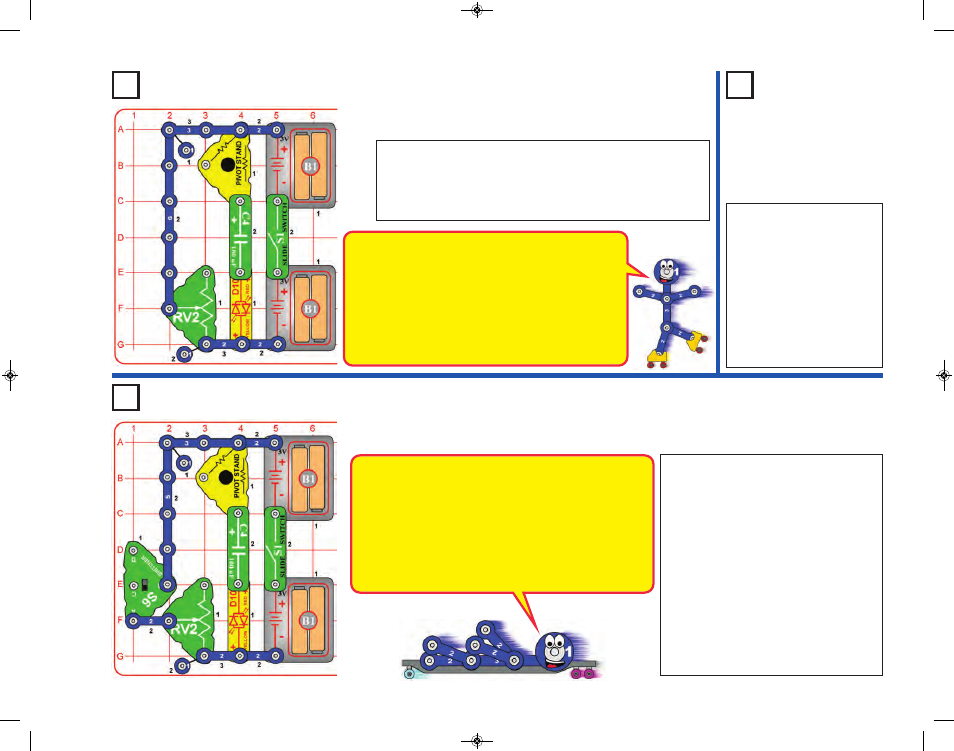
Project 107
Electricity In,
Electricity Out
Turn on the slide switch (S1); the red/yellow bicolor LED (D10)
flashes red. Now turn off the slide switch; the LED flashes yellow.
The lever on the adjustable resistor (RV2) controls the LED
brightness; setting it up makes the flash dimmer but lasting
longer, while setting it down makes the LED flash bright but brief.
Use the preceding circuit but
replace the 100mF capacitor
(C4) with the 1mF capacitor
(C7). The circuit works the
same, but the LED will only
light very briefly, because the
smaller 1mF capacitor stores
much less electricity than the
larger 100mF capacitor. Do
this in a dimly lit room so you
can see the flashes better.
Project 109
The 100mF capacitor (C4) is like a mini rechargeable
battery because it can store electricity. In this circuit, turning
on S1 charges up the capacitor, which holds the electricity
after S1 is turned off. Turning on S6 creates a circuit path
through RV2 for the capacitor to discharge through.
Capacitors store electricity in the form of an electric field
while batteries store it as chemical energy. Because of this,
capacitors can’t store nearly as much electricity as
batteries, but can store and release it much faster.
Modify the preceding 2 circuits to include
the switcher (S6), as shown here. Set the
switcher to the middle position. Turn on the
slide switch (S1); the red/yellow bicolor
LED (D10) flashes red. Now turn off the
slide switch, wait a little, then set the
switcher to the bottom position; the LED
flashes yellow. Set the switcher back to the
middle position, and you are ready to do it
again.
As before, the lever on the adjustable
resistor (RV2) controls the LED
brightness; setting it up makes the flash
dimmer but lasting longer, while setting it
down makes the LED flash bright but brief.
Project 108
Little
Electricity
In/Out
-56-
Mini Rechargeable
Battery
When you turn on the slide switch, the LED (D10) flashes
red as electricity from the batteries charges up the 100mF
capacitor (C4). The capacitor can store electricity, but
can’t store very much, so charges up quickly.
When you turn off the slide switch, the LED flashes yellow as the
electricity in the capacitor discharges through the adjustable
resistor (RV2). The red/yellow bicolor LED shines a different color
now because electricity is flowing in the opposite direction. The
setting on RV2 controls how fast the capacitor can discharge.
SCM-165_Manual_061114.qxp_Layout 1 7/7/14 11:29 AM Page 57