Project 110 mini rechargeable batteries, Project 111 left right bright lights – Elenco Snap Circuits Motion User Manual
Page 58
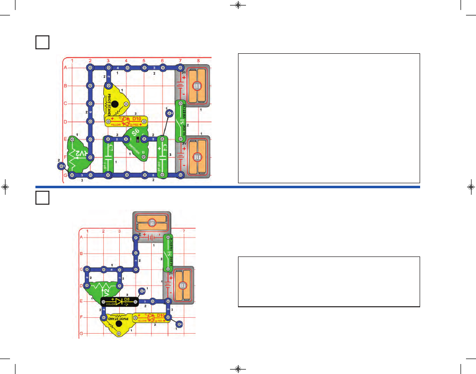
Project 110
Mini Rechargeable Batteries
Turn on the slight switch (S1) and move the lever on the adjustable
resistor (RV2) around. The LEDs (D8 & D10) are bright if the lever is to
the far left or far right, and dim if the lever is in the middle.
Try removing the color LED (D8). This makes it easier to see the effects
on the red/yellow LED (D10), because it will not be blinking anymore.
You can also reverse the orientation of the red/yellow LED.
Project 111
Left Right
Bright Lights
-57-
This circuit is similar to the preceding three circuits, but uses the
switcher (S6) as a three-way switch so it is easier to compare the
difference between the 1mF & 100mF capacitors (C7 & C4).
With S6 set to the middle position: neither capacitor is connected to
the circuit, so nothing will happen when you turn the slide switch (S1)
on or off.
With S6 set to the top position: The 1mF capacitor (C7) is connected
to the red/yellow bicolor LED (D10). Turn on S1; the LED flashes yellow
as C7 charges. Turn S1 off; the LED flashes red as C7 discharges. The
adjustable resistor (RV2) controls the capacitor discharge rate, making
the LED either flash brighter or stay on longer.
With S6 set to the bottom position: The larger 100mF capacitor (C4)
is connected to the red/yellow LED. Turn on S1; the LED flashes yellow
as C7 charges. Turn S1 off; the LED flashes red as C7 discharges. The
LED is brighter because C4 can store a lot more electricity than C7
could. The adjustable resistor (RV2) controls the capacitor discharge
rate, making the LED either flash brighter or stay on longer.
SCM-165_Manual_061114.qxp_Layout 1 7/7/14 11:29 AM Page 58