Project 120 lots at once, Project 121 electrical circle – Elenco Snap Circuits Motion User Manual
Page 62
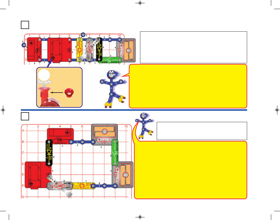
Project 120
Lots at Once
Rearrange the parts in the preceding circuit to make this one,
which has them connected in a loop. Turn on the slide switch (S1).
The LEDs (D8 & D10) light, but the geared motor (GM), air fountain
(AF), and light motor (M7) do nothing. Snappy knows why.
Project 121
Electrical Circle
-61-
Place the spout
on top of the air
fountain and the
ball in the air flow.
Spout
Build the circuit, but note that the air fountain (AF) is placed over the middle of
the 5-snap and 6-snap wires. Place the spout on top of the air fountain and
place the ball in it. Turn on the slide switch (S1).
Lots of stuff should be happening - the geared motor (GM) shaft spins, the ball
in the air fountain moves (it may rise into the air, or may just spin around),the
light motor (M7) spins and lights, and the LEDs (D8 & D10) are on.
You may place the merry-go-round base on the geared motor, but this is not necessary.
Here five components (GM, AF, D10, M7, & D8) are all connected in parallel, so the
electric currents flowing through them can be different, and they are basically
independent of each other. Electricity flows out of the batteries, divides among the five
components, then recombines to flow through the switch and back into the batteries.
Each component gets what it needs from the batteries (unless the batteries are too weak
to supply enough), and all work properly. Also, if one breaks, the others keep working.
Note: this circuit connects the LEDs (D8 & D10) directly to the batteries without a resistor
or other device to limit the current. Normally this could damage an LED, but your Snap
Circuits
®
LEDs have internal resistors added to protect them from incorrect wiring, and
will not be damaged. They are connected directly to the batteries in this circuit to help
demonstrate how parallel circuits work.
Compare this circuit to the preceding one. Here the same five components (GM, AF, D10,
M7, & D8) are all connected in series, so the electric current flowing through them must
be the same, and each affects the others. Electricity flows in a loop, from the batteries,
through each component, and then back into the batteries. Here the component with the
most resistance limits the flow of electricity. In this circuit the LEDs (D8 & D10) have the
most resistance due to their internal protection resistors (see above). The geared motor,
air fountain, and light motor are unable to function because the LED resistance limits the
current too much, though the electrical resistance of these devices is having an additional
small limiting effect on the current flow.
A second battery holder was added to this circuit because the combined turn-on voltage
of both LEDs (about 1.5V each) may be too high to make anything happen with just one
set of batteries (3V). You can try replacing one battery holder with a 3-snap wire and see
if the LEDs turn on.
Connecting parts in series makes the wiring less complex (especially important when the
components are far apart), makes it easier to protect sensitive devices, and can avoid
wasting energy (making batteries last longer).
SCM-165_Manual_061114.qxp_Layout 1 7/7/14 11:29 AM Page 62