About your snap circuits, Parts, Electronic modules – Elenco Snap Circuits Motion User Manual
Page 11: Transistors, Leds
-10-
About Your Snap Circuits
®
Parts
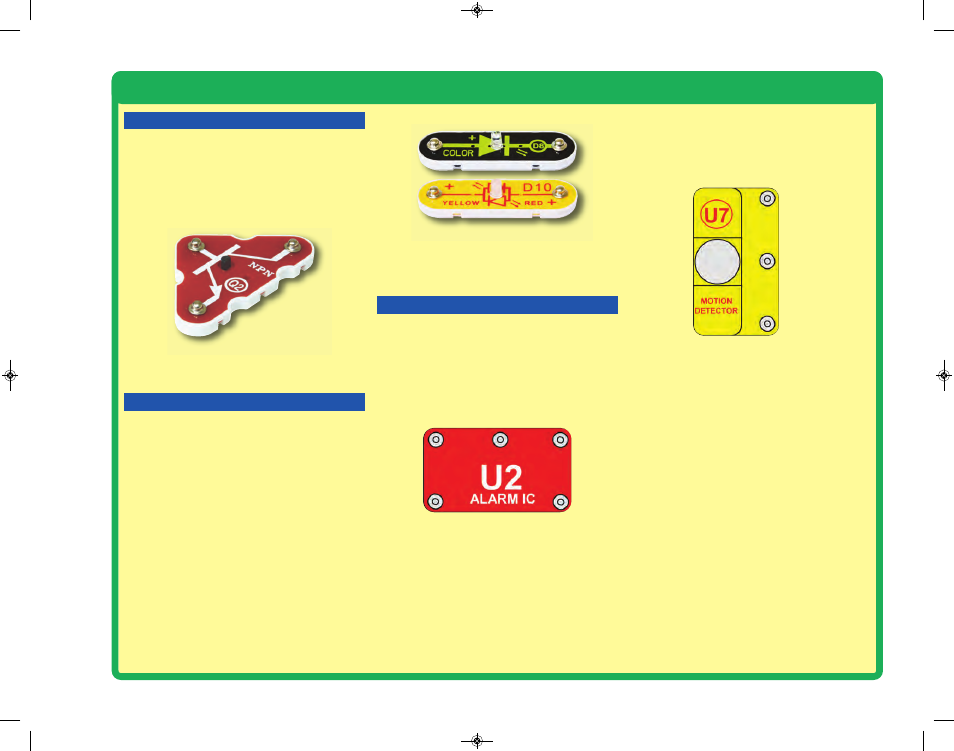
ELECTRONIC MODULES
IN1
(–)
IN2
IN3
OUT
Connections:
IN1, IN2, IN3 - control inputs
(–) - power return to batteries
OUT - output connection
Connect control inputs to (+) power to make five
alarm sounds, see project 39 for an example of
proper connections.
The alarm IC (U2) contains a specialized sound-
generation integrated circuit (IC) and other
supporting components (resistors, capacitors,
and transistors) that are always needed with it.
A schematic for it is available at
www.snapcircuits.net/faq.
The motion detector (U7) contains an infrared
detector, amplifier-filter circuit, and timing circuit.
A schematic for it is available at
www.snapcircuits.net/faq.
All objects (including people and animals)
produce infrared radiation due to the heat in
them. Infrared radiation is similar to visible light
but has a longer wavelength that our eyes cannot
detect. The lens on top of the motion detector
module filters and focuses the radiation, it is most
sensitive to the radiation produced by our bodies.
Inside the motion detector module is an infrared
detector with pyroelectric crystals, which create
a tiny voltage when exposed to infrared radiation.
A circuit amplifies and filters this voltage, but only
responds to changes in the radiation level - so is
only triggered by moving objects (motion). When
motion is detected a timing circuit is used to
control other snap circuits devices for a few
seconds, such as an alarm.
(+)
OUT
(–)
Connections:
(+) - regulated power from batteries
(–) - power return to batteries
OUT - output connection
Lens
LEDs (D8 & D10)
TRANSISTORS
The NPN transistor (Q2) uses a small electric
current to control a large current, and is used in
switching, amplifier, and buffering applications.
Transistors are easy to miniaturize, and are the
main building blocks of integrated circuits
including the microprocessor and memory
circuits in computers.
LEDs
The color LED (D8) and red/yellow bicolor
LED (D10) are light emitting diodes, and may be
thought of as a special one-way light bulbs. In the
“forward” direction, (indicated by the “arrow” in
the symbol) electricity flows if the voltage
exceeds a turn-on threshold (about 1.5V for red,
slightly higher for yellow, about 2.0V for green,
and about 3.0V for blue); brightness then
increases. The color LED contains red, green,
and blue LEDs, with a micro-circuit controlling
then. The red/yellow bicolor LED contains red &
yellow LEDs in connected in opposite directions.
A high current will burn out an LED, so the
current must be limited by other components in
the circuit (though your Snap Circuits
®
LEDs
have internal resistors to protect against incorrect
wiring). LEDs block electricity in the “reverse”
direction.
NPN Transistor (Q2)
SCM-165_Manual_061114.qxp_Layout 1 7/7/14 11:28 AM Page 11