Project 112 charge & discharge, Project 113 super charge & discharge, Project 114 mini charge & discharge – Elenco Snap Circuits Motion User Manual
Page 59
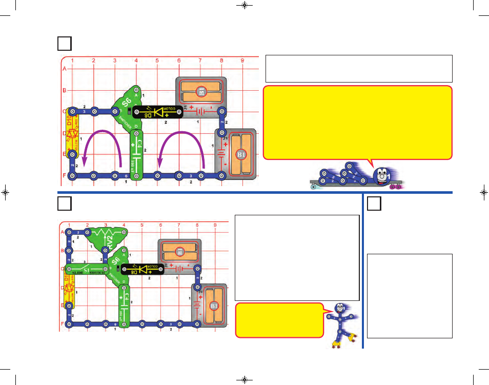
Project 112
Charge & Discharge
Set the switcher (S6) to the top position; the color LED (D8) flashes. Now
set S6 to the bottom position; the red/yellow bicolor LED (D10) flashes red.
Alternate setting S6 to top and then bottom. The middle S6 position is “off”.
Project 113
Super Charge & Discharge
The adjustable resistor limits the
current flow, slowing down the
discharge of electricity form the
100mF capacitor.
Modify the preceding circuit to match this one.
Turn off the slide switch (S1); now the adjustable
resistor (RV2) controls how quickly the 100mF
capacitor (C4) discharges through the red/yellow
LED (D10). Setting RV2 to the left makes D10
flash brightly but briefly; setting RV2 to the right
makes the LED dimmer but it stays on longer.
When the slide switch (S1) is on, the
adjustable resistor is bypassed, making the
circuit the same as the preceding one. This
makes it easy for you to compare the circuits.
Use the preceding circuit but
replace the 100mF capacitor
(C4) with the 1mF capacitor
(C7). The circuit works the
same, but the LED will only
light very briefly, because the
smaller 1mF capacitor stores
much less electricity than the
larger 100mF capacitor. Do this
in a dimly lit room so you can
see the flashes better.
Project 114
Mini Charge
& Discharge
-58-
When the switcher (S6) is set to the top position, points C & D (marked directly
on S6) are connected. When S6 is set to the bottom position, points B & D on
it are connected. When S6 is set to the middle position, nothing is connected.
When C & D are connected (S6 to top), electricity from the batteries
quickly charges up the 100mF capacitor (C4) through the color LED (D8),
making the LED flash. The charged capacitor holds its charge even if S6
is turned off, or if C4 is temporarily removed from the circuit.
When B & D are connected (S6 to bottom), the electricity in the capacitor
quickly discharges through the red/yellow LED (D10), making it flash.
SCM-165_Manual_061114.qxp_Layout 1 7/7/14 11:29 AM Page 59