Project 91 slow off tilt light – Elenco Snap Circuits Motion User Manual
Page 52
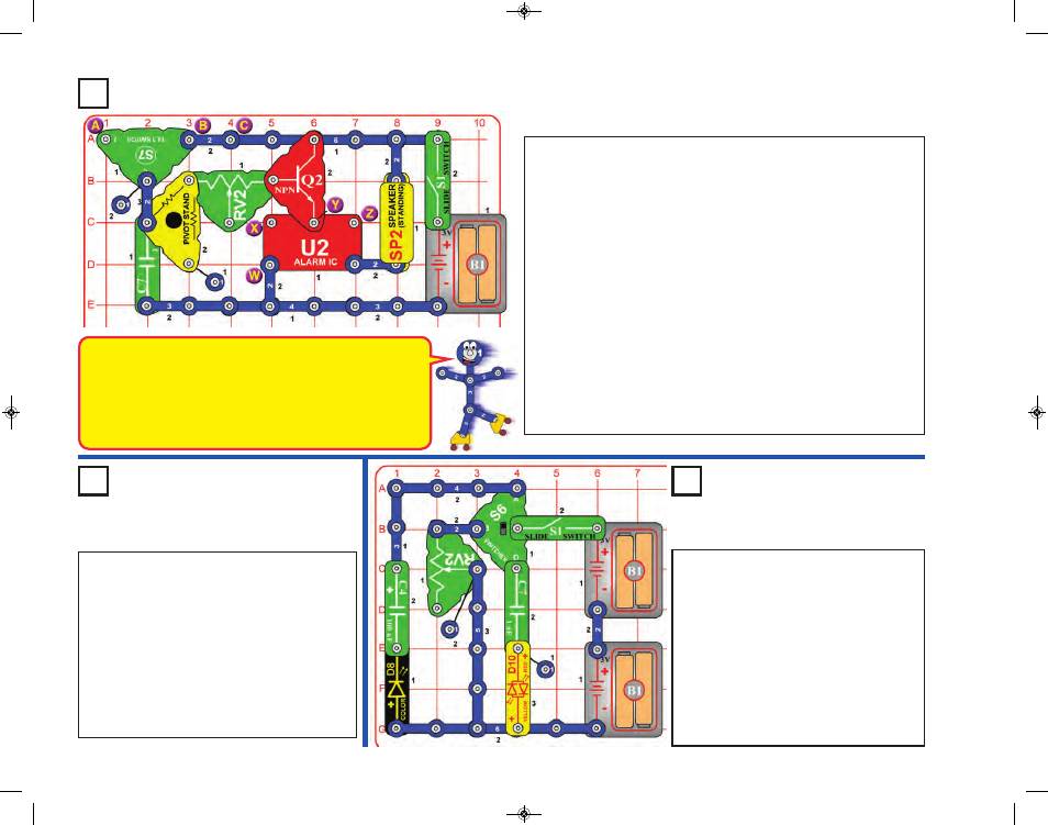
Turn on the slide switch (S1), then alternate
between setting the switcher (S6) to the top
and bottom positions. Try this at different
settings on the adjustable resistor (RV2).
Next, swap the locations of the color LED
(D8) and red/yellow bicolor LED (D10).
Next, reverse the orientations of the LEDs
(D8 & D10).
The LEDs (D8 & D10) will light, sometimes
briefly and dimly, as the capacitors are
charged and discharged.
Project 92
Switcher Fun
Project 90
Slow Off Tilt Alarm
Build the circuit and turn on the slide switch (S1). An alarm sounds if
the circuit is moved, or tilted in some directions. The alarm stays on for
about 2 seconds after the tilt is removed. Moving the lever on the
adjustable resistor (RV2) won’t do anything.
If the circuit does not shut off when left alone on a flat surface, then tilt
it slightly so it turns off.
Remove the 2-snap wire between points B & C, and connect the red
jumper wire between points A & C. Now the alarm is activated by
different tilt angles.
If you place keep in the 2-snap wire between points B & C and connect
the red jumper wire between points A & B, then the circuit will be so
sensitive to tilt that the alarm may be difficult to shut off.
Also, you can change the alarm sound by using a 1-snap wire and a 2-
snap wire to make a connection between points W & X, or X & Y, or Y
& Z on the alarm IC (U2).
Finally, replace the 1mF capacitor (C7) with the 100mF capacitor (C4).
Now the alarm stays on much longer, and may appear to never shut off.
Project 91
Slow Off Tilt Light
Use the preceding circuit but replace the speaker
(SP2) with the color LED (D8, “+” on top) or the
red/yellow bicolor LED (D10, in either
orientation). The circuit works the same but has
light instead of sound. Try it with both LEDs (D8
& D10), separately.
The variants in project 90 regarding different
connections to points A-B-C and W-X-Y-Z, and
the 100mF capacitor (C4) can also be used here.
Adding the connection between W & X may be
the most interesting variant.
-51-
When tilt is detected, the 1mF capacitor (C7) is charged through the
tilt switch (S7). When tilt is removed, the capacitor discharges through
the resistors in the pivot stand and RV2, and through the NPN
transistor (Q2). The alarm stays on as the capacitor discharges.
You can make the alarm shut off faster after tilt is removed by
disconnecting C7, or by connecting the black jumper wire across the
pivot stand or adjustable resistor.
SCM-165_Manual_061114.qxp_Layout 1 7/7/14 11:29 AM Page 52