Project 49 slow merry-go-round, Project 50 adjustable merry-go- round with lights – Elenco Snap Circuits Motion User Manual
Page 35
Insert some of the cardboard figures into the 3 slots
on the edge of the merry-go-round base (the figures
may need to be punched out of a cardboard sheet).
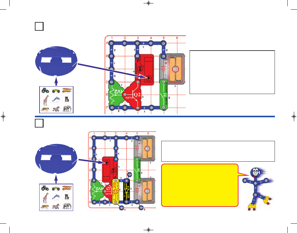
Build this circuit and mount the merry-go-round base
onto the shaft on the geared motor (GM).
Turn on the slide switch (S1), and adjust the speed
of the merry-go-round using the lever on the
adjustable resistor (RV2). Most of the speed control
will be over a small part of RV2’s adjustment range.
Project 49
Slow Merry-Go-Round
Modify the preceding circuit to make this one. Set the lever on the
adjustable resistor (RV2) to the top. Turn on the slide switch (S1), and
use the lever on the adjustable resistor to set the brightness of the LEDs
(D8 & D10) and the speed of the merry-go-round base.
This circuit uses the NPN transistor (Q2) and
adjustable resistor (RV2) to control the speed
of the geared motor (GM). A small electric
current into the transistor through RV2 and the
LED (D10) controls a larger current into the
transistor through the geared motor. RV2
cannot be used to control the geared motor
directly, because its high resistance would
prevent the geared motor from operating.
Project 50
Adjustable Merry-Go-
Round with Lights
-34-
SCM-165_Manual_061114.qxp_Layout 1 7/7/14 11:29 AM Page 35