Juster, Project 74 two-way double brightness ad, Project 75 – Elenco Snap Circuits Motion User Manual
Page 47
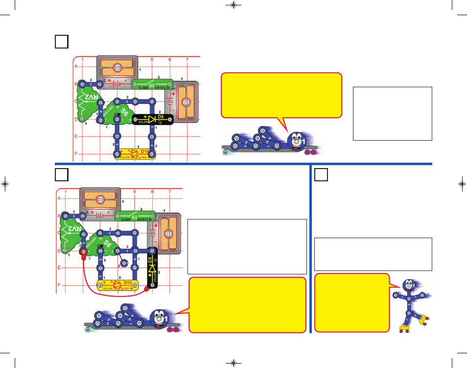
Project 74
Two-Way Double
Brightness Ad
juster
Build the circuit and turn on
the slide switch (S1). Use the
switcher (S6) to set the color
of the red/yellow bicolor LED
(D10) and use the adjustable
resistor (RV2) to set the
brightness of the LEDs.
The color LED (D8) contains separate red,
green, and blue lights, with a micro-circuit
controlling them. The controlling circuit briefly
turns the LED off between colors, which also
shuts off the red/yellow LED because both are
connected in series.
Project 75
Parallel Double
Brightness
Adjuster
Project 76
Dim Double
Brightness
Adjuster
Use the preceding circuit but replace one of
the battery holders (B1) with a 3-snap wire.
The LEDs (D8 & D10) are dimmer now,
especially on some settings for RV2.
In this circuit the current-limiting
effects of RV2 are even more
dominant than in the preceding
circuit, due to the lower voltage.
Voltage is like electrical pressure
pushing current through a circuit,
and this circuit has one battery
holder (3V) instead of two (6V
total).
-46-
This circuit has both LEDs (D8 & D10) connected in
parallel with a single resistor (RV2) limiting the
current through both. The LEDs have only limited
brightness because the current through RV2 divides
between them.
Notice how the red color in D8 is brighter than the
green & blue colors it produces. This is because red
is easier for the LED to produce than green & blue.
Build the circuit and turn on the slide switch
(S1). Use the switcher (S6) to set the color of
the red/yellow bicolor LED (D10) and use the
adjustable resistor (RV2) to set the brightness
of the LEDs.
Try removing the red/yellow bicolor LED from the
circuit and see how it affects the color LED (D8).
SCM-165_Manual_061114.qxp_Layout 1 7/7/14 11:29 AM Page 47