Echelon Mini FX User Manual
Page 32
Mini FX User's Guide
19
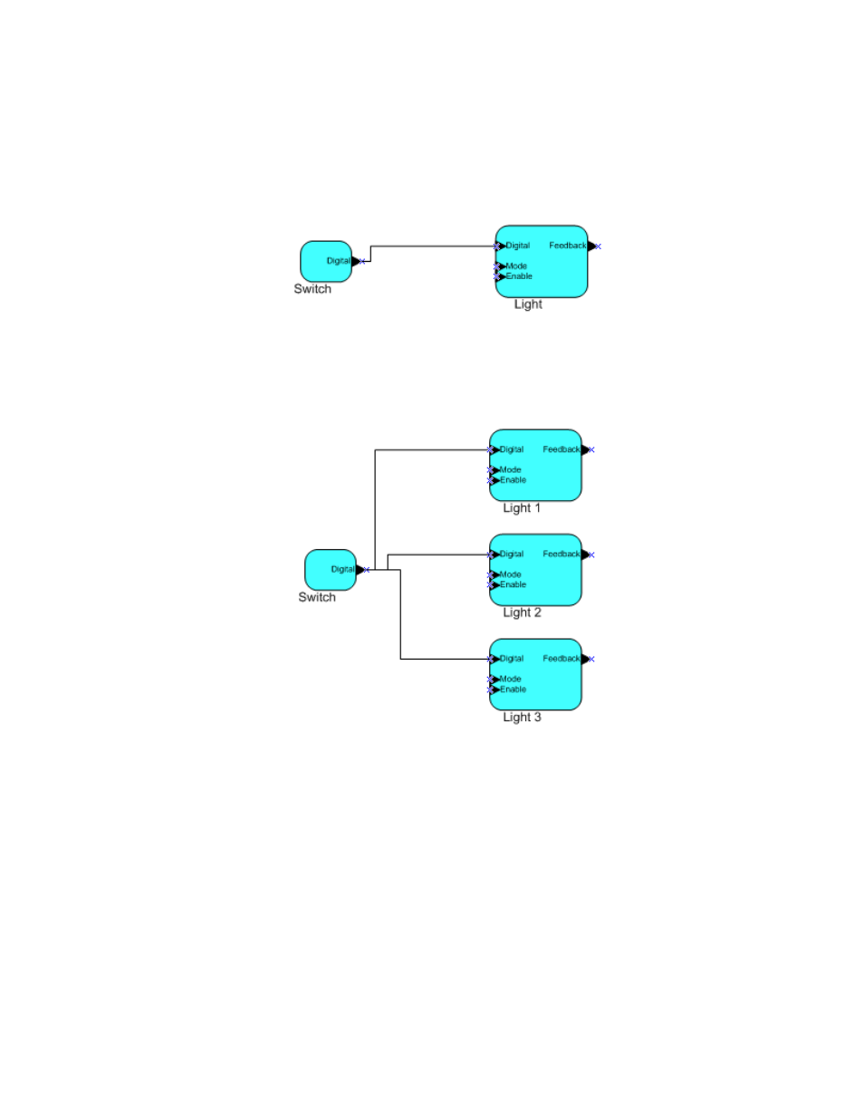
an input network variable that was of the switch type, while an application on a
dimmer-switch device could have an output network variable of the same type. A
network management tool such as the LonMaker Integration Tool could be used to
connect these two devices, allowing the switch to control the lighting device, as shown in
Figure 1.4:
Figure 1.4 Network Variable Connection
A single network variable may be connected to multiple network variables of the same
type but opposite direction. Figure 1.5 shows the same switch being used to control three
lights:
Figure 1.5 Network Variable Fan-Out Connection
The application program in a device does not need to know where input network variable
values come from or where output network variable values go. When the application
program has a changed value for an output network variable, it simply assigns the new
value to the output network variable.
Through a process called binding that takes place during network design and
installation, the device is configured to know the logical address of the other device or
group of devices in the network expecting that network variable’s values. The device’s
embedded firmware assembles and sends the appropriate packet(s) to these destinations.
Similarly, when the device receives an updated value for an input network variable
required by its application program, its firmware passes the data to the application
program. The binding process thus creates logical connections between an output
network variable in one device and an input network variable in another device or group
of devices.