Lonworks network, Applying power to the i.lon 600, 3 lonworks/ip channels background & definition – Echelon i.LON 600 LonWorks/IP Server User Manual
Page 22: Orks, Network, Applying power to the i .lon 600
Section 1: Setting Up and Using the i.LON 600 L
ON
W
ORKS
/IP Server
L
ON
W
ORKS
Network
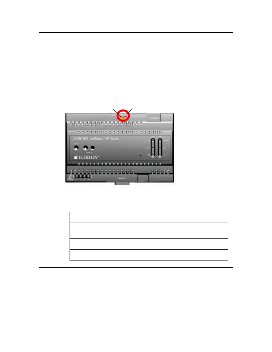
The i.LON 600 is provided with one of two types of L
ON
W
ORKS
channels: TP/FT-10 free
topology twisted pair (Models 72601 and 72603), or TP/XF-1250 (models 72602 and
72604). The twisted pair interfaces are polarity-insensitive and require connecting the
twisted pair to terminals 5 and 6.
The screw terminals accept 0.34 – 4.0mm
2
(22 – 12AWG) gauge solid wire. The
optimum tightening torque for the screw terminals is 0.75mm (6 lbs. in.) maximum. The
ideal flathead screwdriver tip width is 3mm (0.12”). Wires should be stripped to a length
of 7mm (0.28”). Although not required, you should use a soldering iron to tin the stripped
lengths of any stranded wires to prevent fraying and inadvertent contact with adjacent
terminals
LON A
LON B
Figure 7. Twisted Pair Terminals
Table 4. L
ON
W
ORKS
TP/FT-10 Network Connections
Screw Terminal
Enclosure Marking
L
ON
W
ORKS
Network
Connection
5
LON B
TP/FT-10 twisted pair, TP/XF-1250
twisted pair
6
LON A
TP/FT-10 twisted pair, TP/XF-1250
twisted pair
Applying Power to the i.LON 600
Once you have mounted the i.LON 600 and connected all wiring, apply AC mains power
to the unit.
The LEDs on the i.LON 600 will flash for less than a minute as the unit boots. Once the
unit is powered and operational, the green Power LED will stay solid ON.
14
Mounting, Cabling and Connections