O o o o, Chart 1, field power supply connections – Carrier 38AH044-134 User Manual
Page 7
Attention! The text in this document has been recognized automatically. To view the original document, you can use the "Original mode".
o o o o O O O O O
o o o o
V I E W 5 - 5
TOP VIEW OF CONTROL BOX SHELF
WITH FIELD POWER SUPPLY CONNECTIONS
4
5 / 8 '
ni7mml
RELIEF VALVES LOCATED ON
COMPRESSORS A2 AND B2 ARE EQUIPPED
WITH A 3/8' SAE FLARE FOR
FIELD CONNECTION
SCALE 1:8
CONTROL
BOX END
-3 7/16
C392mm]
MTG HOLES
(8) MTG HOLES
17/32' DIA
C13tnmJ
HINGED ACCESS
PANEL
(CONTROL SIDE)
HINGED ACCESS
PANEL
(POWER SIDE)
- 7 - 4 1 1 / 1 6 ---------
t2252mm)
MTG HOLES
- 7 - 7 1 1 / 1 6 ' ---------
[2328mm]
BASE OVERALL
LEFT-END VIEW
? ' - l l 9 / 1 6 '
(2428mm]
-1
1/2
[38mm]
MTG HOLES
(4) RIG HOLES
2 5/8' DIA
[67mm]
2 - 3 1 1 / 1 6 '
[703 mm]-
RIG HOLES
[764mm] CKT A
2 -10'-
[8S7mir] CKT B
RIGHT-END VIEW
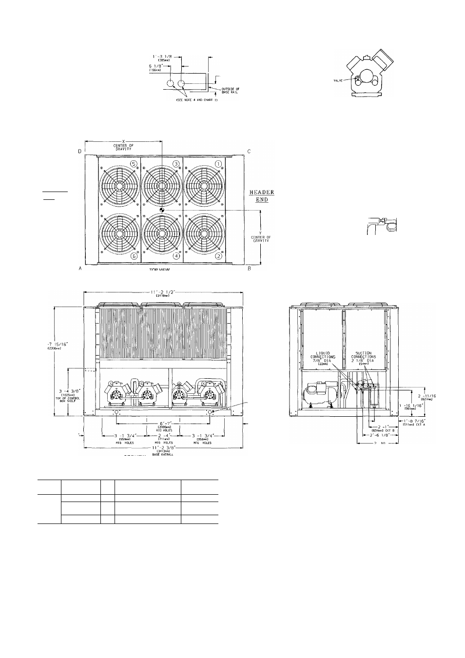
Chart 1, Field Power Supply Connections
UNIT
38AH
VOLTAGE
Hz
DIAMETER — in. (mm)
QUANTITY
208/230
60
3% (92)
2
104
460, 575,
380
60
3% (92)
1
346, 380/415
50
3 5
/e (92)
1
LEGEND
C
— Copper Fin Coils
MTG
— Mounting
SAE
— Society of Automotive Engineers
NOTES;
1 The approximate operating weight of the unit is:
38AH-104—
5435 lb (2465 kg)
38AH-104-C
6160 lb (2794 kg)
2 Unit must have clearances for airflow as follows:
Top — Do not restrict in any way
Ends — 5 ft [1524 mm]
Sides —6 ft [1829 mm]
3 Mounting holes may be used to mount unit to concrete pad They are not
recommended for mounting unit to spring isolators
4 Two 3%" (92-mm) dia holes are recommended for parallel conductors on
208/230
V
units
5 Circled numerals in Top View refer to condenser fans by position
6. If spring isolators are used, a perimeter support channel between the unit
and the isolators is recommended
7 See Table 1 for rigging center of gravity (Dimensions X,Y) See Table 2A
and 2B for A-D corner weights
Fig. 4 — Dimensions — Unit 38AH104