38ан124,134, A caution, Caution – Carrier 38AH044-134 User Manual
Page 31: Lb2j
Attention! The text in this document has been recognized automatically. To view the original document, you can use the "Original mode".
<е
38АН124,134
MODULE
124А OR 134A
ТВЗ
Ф
TIME
GUARD®
CONTROL
SDR2 ^
CCPS -ÆA^
MODULE
124B OR 134B
ACCESSORY
RELAY
PACKAGE
CR1
—^—II—vio
CR2
TB3
TIME
GUARD®
CONTROL
SDR2 ^
—It—^
CCPS
SDR2
;cAi
'CA2]
SDR2
|] Щ И
L
j
U_SEE
NOTE 2
_____ I
|T
ls
1
I
T
lls
I
LB2j
I___ I
-
yel
A
CAUTION
Internal TSR-01 relay contacts are rated for 1 amp/24 vac.
q
-COMMUNICATION
OUT
- COMMUNICATION IN
CARRIER COMMUNICATING
TEMP MONITOR THERMOSTAT
.(MODEL MS(T)01ES)
++-WHtTE--
e
«ED— e
BLUE— e
____YELLOW- e
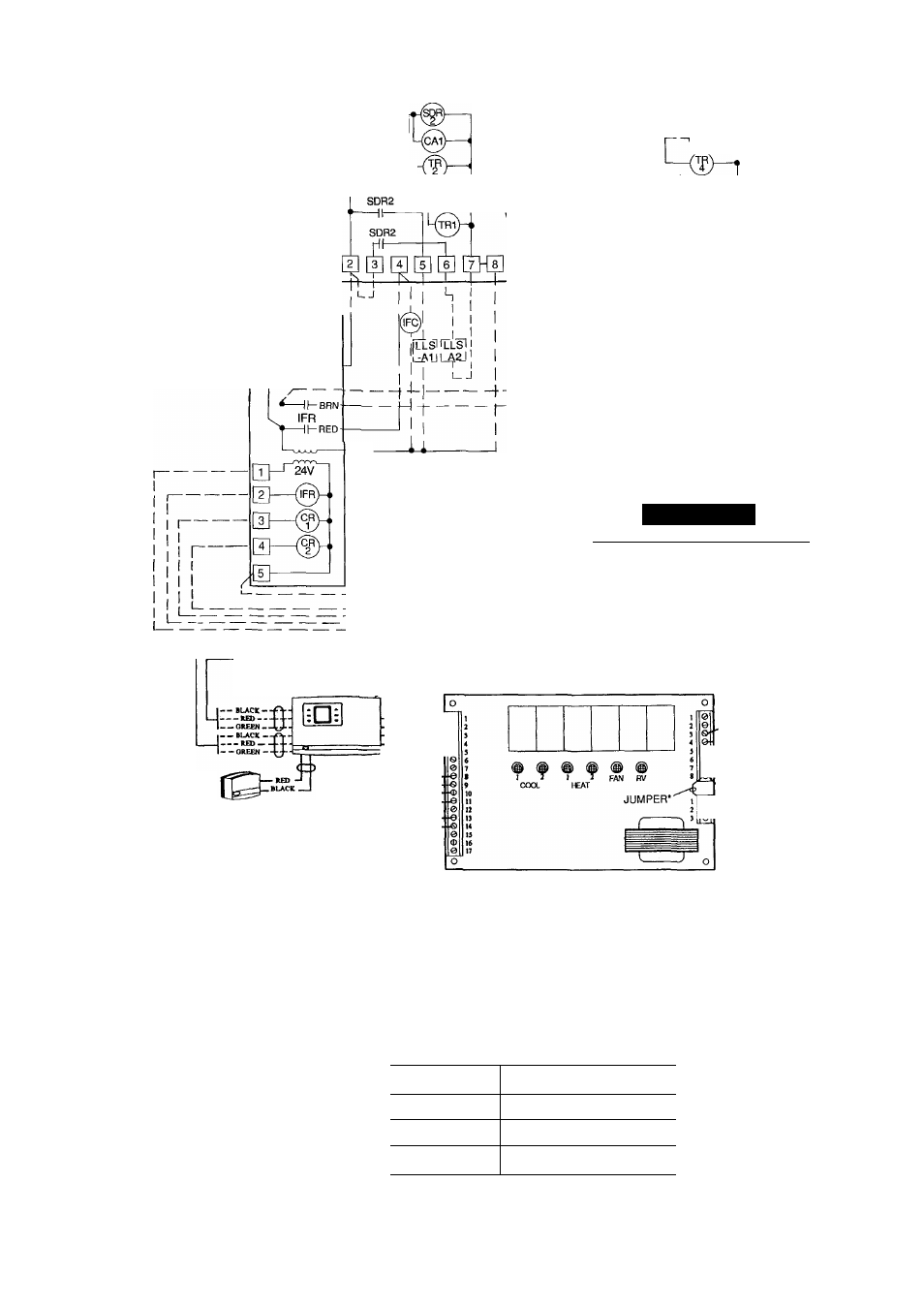
-- - — OREEN-- REMOTE ROOM TEMP SENSOR •Jumper removed only when separate 24-v transformer power source is used to power the TSR-01 relay pack TSR-01 RELAY PACK CIRCUIT BOARD ----------- fan "I 1 HEAT 2 -i -------- HEAT 1 -5 0 '■--------- COOL2-------------‘ I ------- COOL1---------------- ' " —"________ J I —24 VAC (R) 24 VAC (Comrtran) NOTES: 1 Liquid line solenoid valves LLS-A1 and A2 are used for solenoid drop on Module 124A or 134Aon circuit A Liq is a safety feature which prevents refrigerant migration to the compressor during the OFF cycle It is recom mended on all systems and required on systems where 2 Disconnect black wire from CR2 terminal 6; cap loose end and secure Connect new field-supplied wire from CR2 terminal 6 to ТВЗ terminal 1 on module 124B or 134B 3 The TSR-01 relay pack requires 10 va Factory wiring is in accordance with NEC; field modi fications or additions must be in compliance with all ap 5 Wiring for field power supply must be rated 75 C mini mum Use copper, copper-clad aluminum, or alumi num conductors Maximum incoming wire size for each 6. Terminal blocks (ТВЗ) are for external field control con nections Control connections must be class 1 wiring 10 Field-supplied components {IFC, LLS-A1,A2, and LLS-B1 ,B2) must have a maximum sealed coil rating 230 vac) Thermostats must have a minimum pilot cluty rating of 300 va (2 5 amps at 120 vac) Units have 175 va of power available for field-installed accessories. To minimize voltage drop, the following wire sizes are recommended: LENGTH — Ft(M) INSULATED WIRE — AWG (35 C Minimum) Up to 50 (15.2) No 18 50-75 No 16 More Than 75 No 14 LEGEND AWG — American Wire Gage C — Compressor Contactor CCPS — Capacity Control Pressure Switch CR — Control Relay HD — Heating Device IFC — Indoor-Fan Contactor IFR — Indoor-Fan Relay kcmil — Thousand Circular Mils LLS — Liquid Line Solenoid NEC — National Electrical Code (U S.A Standard) R — Heating Relay (field- supplied 24-v sealed coil, 10 va maximum rating) RV — Reversing Valve SDR — Solenoid Drop Relay TB — Terminal Block TR — Timer Relay Factory Wiring ------------- Field Wiring Fig. 23 — Field Wiring, One 2-Stage Thermostat — Units 38AH124 and 134 31
uid line solenoid valves LLS-B1 and B2 are used for
solenoid drop for Module 124B or 134B. Solenoid drop
piping exceeds 75 ft (22 9 m) in length
4
plicable codes
terminal block is 500 kcmil.
of 30 va each (0 25 amp at 120 vac and 0 13 amp at
Replacement of factory wires must be with type 105 C
wire or its equivalent.
Field-supplied liquid line solenoid valves installed at the
evaporator are required on all units
(15.2-22.9)
(22.9)