Capacity control, Fig. 44 — unloader location and settings – Carrier 38AH044-134 User Manual
Page 45
Attention! The text in this document has been recognized automatically. To view the original document, you can use the "Original mode".
Winter Stsrt Control — A2V4-minute low-pressure switch
(LPS) bypass function in the timer prevents nuisance LPS
trips during start-up in low-ambient conditions.
High-Pressure Switch — This switch has nonadjust-
able settings. Figure 29 shows connection on a cylinder head.
See Table 18 for pressure switch settings.
NOTE: High-pressure switch must be removed from cylin
der head before removing compressor from the unit.
TO CHECK — Slowly close the discharge shutoif valve un
til the compressor shuts down. This should be at approxi
mately 426 psig (2935 kPag). Slowly open the valve. When
the pressure drops to approximately 320 psig (2205 kPag),
the pressure switch resets. To reenergize the control cirenit,
manually switch the fan circuit breaker olf and then on. The
compressor starts again under Time Guard® controls.
Low-Pressure Switch — The low-pressure switch (LPS)
has fixed nonadjustable settings. It is located at the pump
end of the compressor above the bearing head. See Table 18
for pressure switch settings.
TO CHECK — Slowly close the suction cut-off valve and
allow the compressor to shut down. This should occur at ap
proximately 27 psig (186 kPag). Slowly open the valve. The
compressor restarts under Time Guard control when the pres
sure builds to approximately 67 psig (462 kPag).
Table 18 — Pressure Switch Settings,
Psig (kPag)
SWITCH
CUTOUT
CUT-iN
High
426 ± 7
320 ± 20
(2935 ± 48)
(2205 ± 138)
Low
27 ± 4
67 ± 7
(186 ± 28)
(462 ± 48)
Capacity Control
38AH044-084 DUAL-CIRCUIT UNITS — Capacity con
trol is achieved by a pressure-actuated cylinder bank un
loader on lead compressor Al. As the cooling load decreases
and the suction pressure drops, the unloader actuates at the
pre-set suction pressure and unloads the cylinder bank. (See
Eig. 44 and Table 18.) The unloading of the compressor cyl
inder bank has no effect on the operation of lag compressor
B2, which is controlled by TC2.
38AH044-084 SINGLE-CIRCUIT UNITS AND MOD
ULES 124A, 124B, I34A, AND 134B — Capacity control
is achieved by a pressure-actuated cylinder bank unloader
on lead compressor AL See Table 16. As the cooling load
decreases and the suction pressure drops, the unloader ac
tuates at the pre-set suction pressure and unloads the cylin
der bank. (See Fig. 44 and Table 19B and 20.) Lag compres
sor A2 is controlled by fixed setting capacity control pressure
switches (CCPSs) as follows:
38AH094,104 — Capacity control is achieved by a pressure-
actuated cylinder bank unloader on the lead compressor
(Al, B1) on each of the 2 refrigeration circuits. As the cool
ing load decreases and the suction pressure drops, the un
loader actuates at the pre-set suction pressure and unloads
the cylinder bank. (See Fig. 44 and Table 20.) The unloading
of the compressor cylinder bank has no effect on the opera
tion of the circuit lag compressor (A2, B2 [except 38AH094,
circuit B]) which is controlled by fixed setting capacity con
trol pressure switches (CCPSs) as follows:
CUT-iN —
CUTOUT —
Psi (kPa)
Psi (kPa)
CCPS 1
83 (572)
63 (531)
CCPS 2
80 (551)
53 (365)
CCPS
— Capacity Control Pressure Switch
Pressure Relief — High-side pressure relief is pro
vided by a fusible plug in the liquid line at the service valve.
For low-side pressure relief, a fusible plug is inserted in the
side of the accumulator (all units except 38AH044-084 dual
circuit, constant-volume units). See Fig. 45. The 38AH044-
084 dual-circuit, constant-volume units have a fusible plug
in the suction tubing. A pressure relief valve installed on the
compressor relieves at 450 psig (3102 kPag) (see Fig. 1-6).
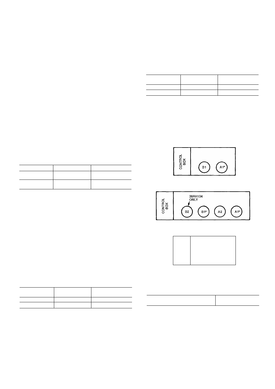
COMPRESSORS - 38AH044-084
DUAL-CIRCUIT UNITS
COMPRESSORS-38AH094,104 UNITS
O
CC X
!=
O
o“
o
©
0
COMPRESSORS - 38AH044.084
SINGLE-CIRCUIT UNITS;
MODULES 124A, 124B, 134A, 134B
CUT-IN —
CUTOUT —
Psi (kPa)
Psi (kPa)
CCPS 1
83 (572)
63 (531)
CCPS 2
80 (551)
53 (365)
CCPS
— Capacity Control Pressure Switch
If suction pressure continues to drop after lead compres
sor A1 unloads and lag compressor A2 is operating, A2 will
stop operating when the suction pressure drops to the CCPS
cutout point.
Unloader Settings
Unioad, psig (kPag)
56 (386)
Load, psig (kPag)
76 (524)
*Unloader location
Fig. 44 — Unloader Location and Settings
45