View 5-5 – Carrier 38AH044-134 User Manual
Page 6
Attention! The text in this document has been recognized automatically. To view the original document, you can use the "Original mode".
ooooooO O O O O
o
OOOO
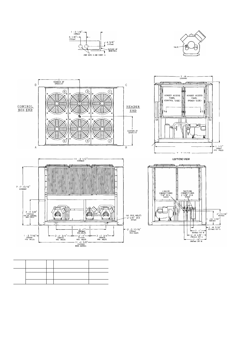
VIEW 5-5
TOP VIEW OF CONTROL BOX SHELF
WITH FIELD POWER SUPPLY CONNECTIONS
RELIEF VALVES LOCATED ON
COMPRESSORS A2 AND B1 ARE EQUIPPED
WITH A 3/8' SAE FLARE FOR
FIELD CONNECTION
SCALE 1:8
(8) MTG HOLES
7/32' DIA
7'-11 9/16'
[2‘128mmD
-7 -4 11/16'-
[2252m(T)
HTG HOLES
-7'-7 11/16'-
C2326n
BASE OVERALL
RIGHT-END VIEW
Chart 1, Field Power Supply Connections
UNIT
38AH
VOLTAGE
Hz
DIAMETER — in. (mm)
QUANTITY
208/230
60
3% (92)
2
094
460, 575,
380
60
3% (92)
1
346, 380/415
50
35/8
(92)
1
LEGEND
C
— Copper Fin Coils
MTG
— Mounting
SAE
— Society of Automotive Engineers
NOTES:
1 The approximate operating weight of the unit is:
38AH-094—
5088 lb (2308 kg)
38AH-094-C
5813 lb (2637 kg)
2 Unit must have clearances for airflow as follows:
Top — Do not restrict in any way
Ends — 5 ft [1524 mm]
Sides — 6 ft [1829 mm]
3 Mounting holes may be used to mount unit to concrete pad They are not
recommended for mounting unit to spring isolators
4 Two 3%" (92-mm) dia holes are recommended for parallel conductors on
208/230
V
units.
5. Circled numerals in Top View refer to condenser fans by position
6 If spring isolators are used, a perimeter support channel between the unit
and the isolators is recommended
7. See Table 1 for rigging center of gravity (Dimensions X,Y) See Table 2A
and 2B for A-D corner weights
Fig. 3 — Dimensions — Unit 38AH094