F: u> u – Carrier 38AH044-134 User Manual
Page 33
Attention! The text in this document has been recognized automatically. To view the original document, you can use the "Original mode".
■f:
u>
u>
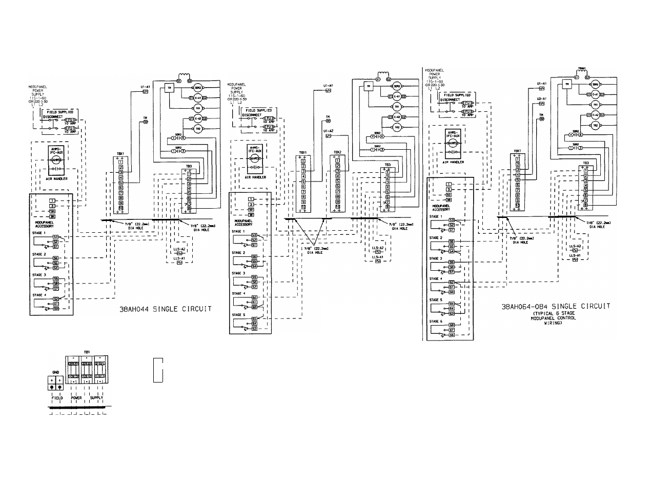
(TYPICAL 4 STAGE
MODUPANEL CONTROL
WIRING)
38AH054 SINGLE CIRCUIT
(TYPICAL 5 STAGE
MODUPANEL CONTROL
WIRING)
\
GM) tCUTRAL
SB
(S)
, + 1
1
[S
m
1
1
1
1
FIELD POWER
as
os
GD
SUPPLY
t I
I____ №C_OIKMNECT__ _
PARALLEL CONDUCTORS
(208/230V)
_1_______ I______ L_l_____ I-
I______ NE£ 0_[SCON№CT____ j
38AH044-064 (ALL VOLTAGES}
SINGLE ENTRY ROVER
NOTES:
.
1. Factory wiring is in accordance with NEC; field modifications or additions must be in com
pliance with all applicable codes.
2. Wiring for field power supply must be rated 75 C minimum. Use copper, copper-clad alu
minum, or aluminum conductors. Maximum incoming wire size for each terminal block is
500 kcmil.
3. Terminal blocks TBS, TBX1, and TBX2 are for external field control connections. Control
connections are to be class 1 wiring.
4
Field-supplied components (IFC, LLS-A1, and LLS-A2) must have a maximum sealed coil
rating of 30 va each (0.25 amp at 120 vac, 13 amp at 230 vac). AHMS IFC-AUX must have
minimum pilot duty rating of 400 va each (3.4 amps at 120 vac, 1.8 amps at 230 vac) each.
5 Replacement of factory wires must be with type 105 C wire or its equivalent.
6. Field-supplied liquid line solenoid valves installed at the evaporator are required on all units.
7
Control has 175 va of power available for field-installed accessories.
Fig. 25 — Field Wiring, Single ModuPanel™ Control, 38AH044-084 Optional Single-Circuit Units