Aim [p ttd – Carrier 38AH044-134 User Manual
Page 36
Attention! The text in this document has been recognized automatically. To view the original document, you can use the "Original mode".
MODUPANEL
POWER
SUPPLY
115-1-60
OR 220-1-50
LI L2
I
^J(23j
ISII221
1211211
11211121M l U l l i
1 + '
^ 1
- V
\
380V, 380/415V,
346V ONLY
FIELD
POWER
,1
I i
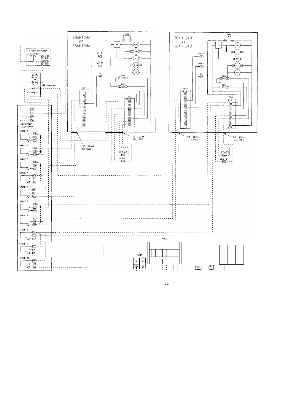
NOTES:
1 Factory wiring is in accordance with NEC Fieid modifications or ad
ditions must be in compiiance with aii appiicabie codes
2 Wiring for fieid power suppiy must be rated 75 C minimum Use cop
per, copper-ciad aiuminum, or aluminum conductors. Maximum in
coming wire size for each terminal block is 500 kcmil
3. Terminal blocks TB3 and TBX1 are for external field control con
nections Control connections are to be class 1 wiring
4 Field-supplied components (IFC, LLS-A1 and A2) must have a maxi
mum sealed coil rating of 30 va each (0 25 amp at 120 vac,
0.13 amp at 230 vac) AHMS IFC-AUX contact must have minimum
pilot duty rating of 400 va each (3 4 amps at 120 vac, 1.8 amps at
230 vac)
5. Replacement of factory wires must be with type 105 C wire or its
equivalent
6. Field-supplied liquid line solenoid valves installed at the evaporator
are required on all units
7 Units have 175 va of power available for field-installed accessories
"I" I
4-
-F
mi
mm
aim
[p
tTD
11
NEC DiSCONNECT
PARALLEL CONDUCTORS
38AH124,134 {208/230V)
DUAL POINT MAIN POWER ENTRY
NEC DISCONNECT
38AH124,134 {ALL VOLTAGES)
DUAL POINT MAIN POWER ENTRY
LEGEND
AHMS
— Air Handler Motor Starter
SDR —
Solenoid Drop Relay
AUX
— Auxilliary
TB —
Terminal Block
C
— Compressor Contactor
TBX —
Terminal Block for Variable
FU
— Fuse
Air Volume Units
GND
— Equipment Ground
TM —
Timer Motor
IFC
— Indoor Fan Control
TR —
Timer Relay
kcmil
— Thousand Circular Mils
TRAN —
Transformer
LLS
— Liquid Line Solenoid
U —
Unloader Solenoid
NEC
— National Electrical Code
( U S A Standard)
—
Factory Wiring
Field Wiring
Fig, 28 — Field Wiring, Single ModuPaneF” Control, Units 38AH124 and 134
36