Preliminary checks – Carrier 38AH044-134 User Manual
Page 38
Attention! The text in this document has been recognized automatically. To view the original document, you can use the "Original mode".
DISCHARGE
CYLINDER
GAS THERMOSTAT HEADS
OIL PRESSURE SWITCH AND
CAPACITY CONTROL
PRESSURE SWITCH CAPILLARIES
MUFFLER
FAN CYCLING
PRESSURE SWITCR
DISCHARGE
GAS
THERMOSTAT
PRESSURE
RELIEF
VALVE
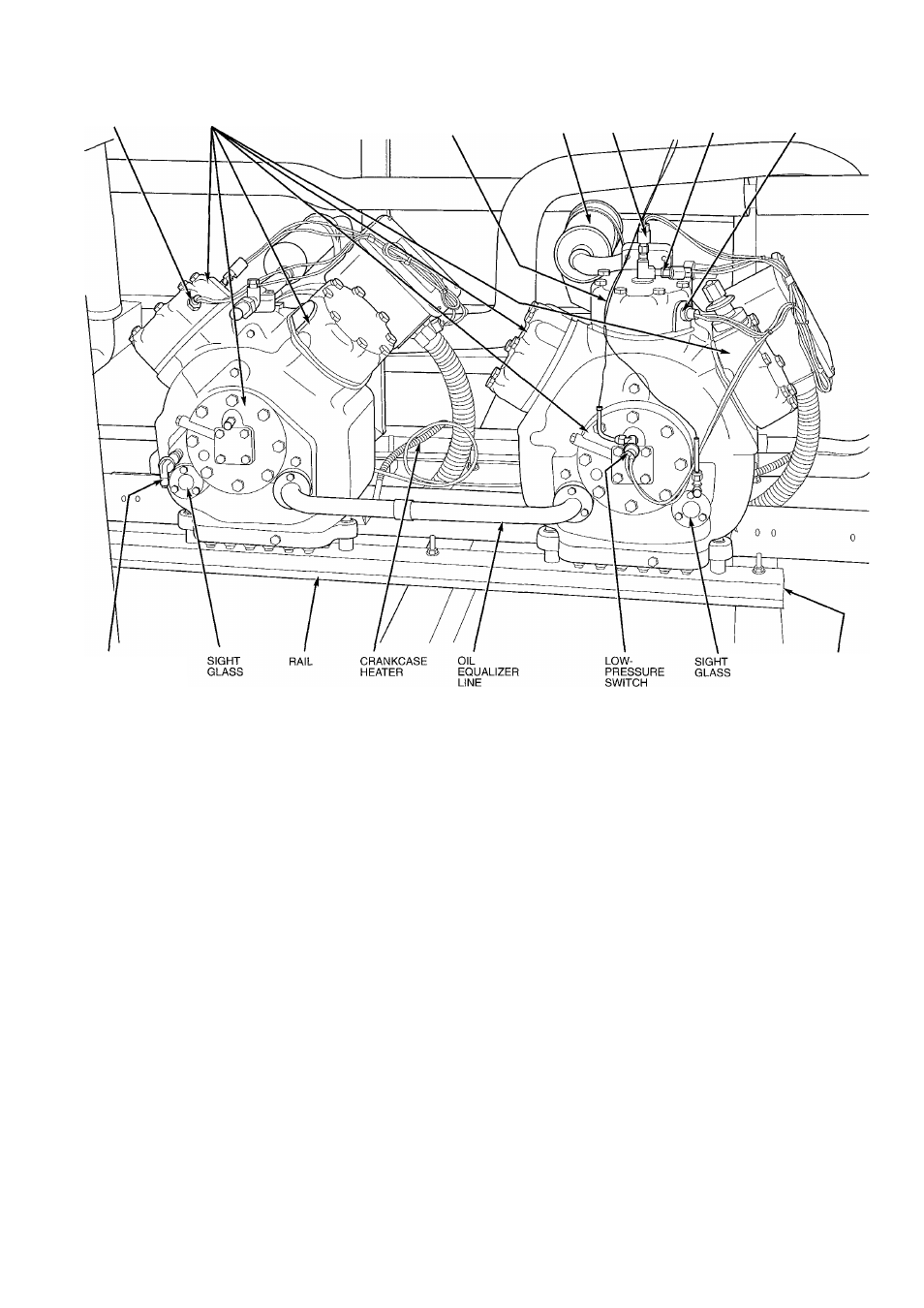
NOTE: Units 38AH044-084 and 38AH124,134 compressors are pan
mounted Units 38AH094 and 104 compressors are mounted on rails.
MOUNTING
SPRING
(HIDDEN)
Fig. 29 — 06E Compressors, Typical
Preliminary Checks
1. Ensure that compressor service valves are backseated.
2. Verify that each compressor on units 38AH044-084, 124,
and 134 floats freely on its mounting springs. Verify that
each compressor on units 38AH094 and 104 floats freely
on its rails.
3. Check that electric power supply agrees with unit name
plate data.
4. Verify that compressor crankcase heaters are securely in
place.
5. Check that compressor crankcase heaters have been on at
least 24 hours.
6. Note that compressor oil level is visible in the sight glass.
7. Recheck for leaks using same procedure as previously out
lined in Step 3 — Make Refrigerant Piping Connections,
page 13
8. If any leaks are detected, evacuate and dehydrate as pre
viously outlined in Step 3 — Make Refrigerant Piping
Connections, page 13.
Proliminary Oil Charge — Each compressor is fac
tory charged with oil (see Table 3A, 3B, 4A, or 4B). When
oil is checked at start-up, it may be necessary to add or re
move oil to bring it to the proper level. One recommended
oil level adjustment method is as follows:
ADD OIL — Close suction shutoff valve and pump down
crankcase to 2 psig (14 kPa). (Low-pressure cutout must be
jumped.) Wait a few minutes and repeat until pressure re
mains steady at 2 psig (14 kPa). Remove oil fill plug above
the oil level sight glass, add oil through plug hole, and re
place plug. Run compressor for 20 minutes and check oil
level.
IMPORTANT: For units with 2 compressors per re
frigeration circuit, both compressors must be running
to adjust the oil level. Two oil level equalizer lines be
tween compressors distribute the oil to each
compressor.
NOTE: Use only Carrier approved compressor oil. Ap
proved sources are: Petroleum Specialties Inc. (Cryol I50A),
Texaco, Inc. (Capella WF-32-150), and Witco Chemical Co
(Suniso 3GS). Do not reuse oil that has been drained out, or
oil that has been exposed to atmosphere.
REMOVE OIL — Pump down compressor to 2 psig
(14 kPag). Loosen the Vi-in. (6.4-mm) pipe plug at the com
pressor base and allow the oil to seep out past the threads of
the plug.
NOTE: The crankcase will be slightly pressurized. Do not
remove the plug, or the entire oil charge will be lost.
Small amounts of oil can be removed through the oil pump
discharge connection while the compressor is running.
38