Carrier 38AH044-134 User Manual
Page 22
Attention! The text in this document has been recognized automatically. To view the original document, you can use the "Original mode".
MODULE CORNER SCREWS (2)
124B POST (4 PER FOR
OR 134B MODULE) MOUNTING
SIDE PANEL
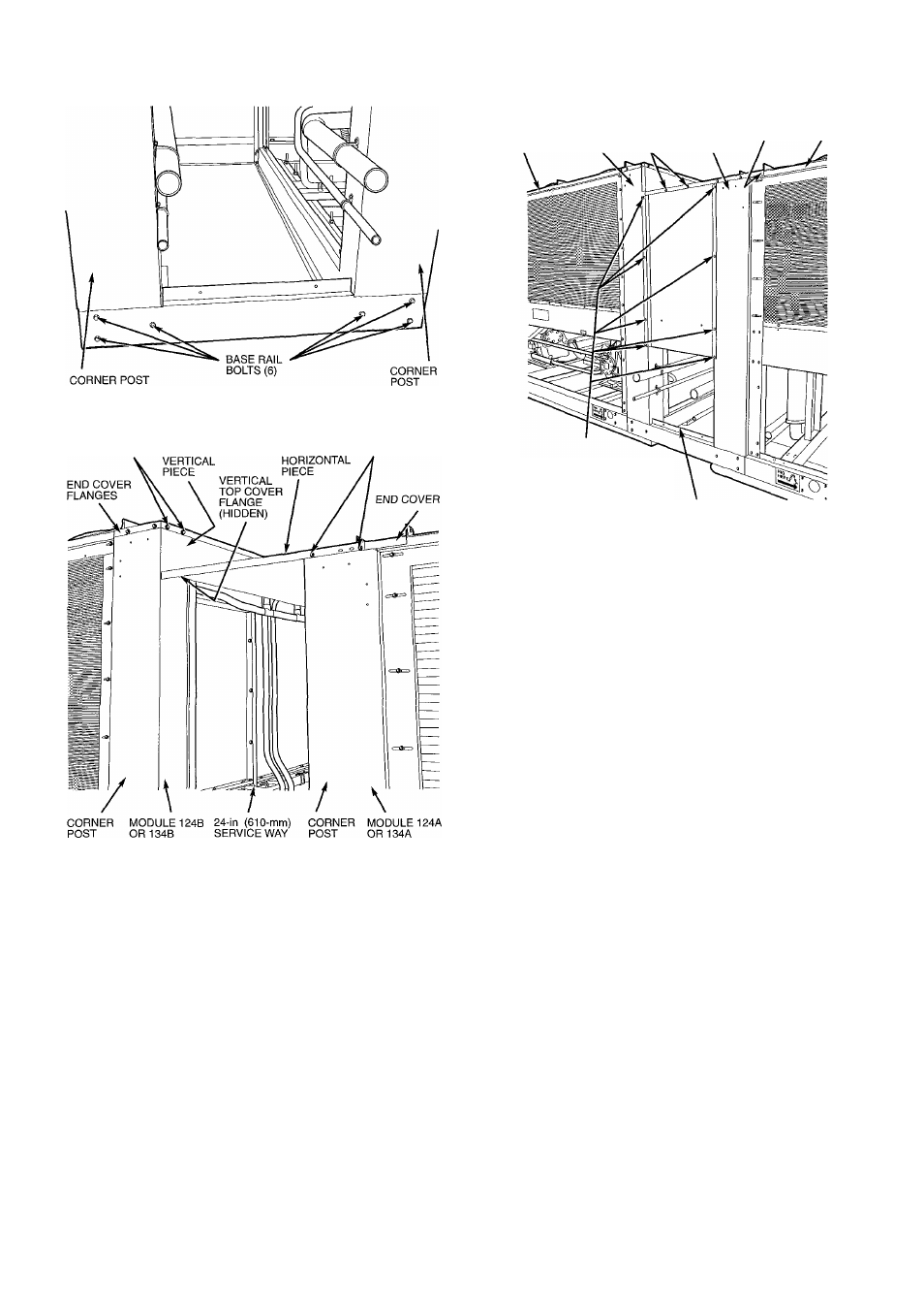
Fig. 17 — Units 38AH124 and 134 with Instailed Trim
Kit Raiis
SCREWS B TOP COVER,
TOP COVER, SCREWS A
Fig. 18- ’ Units 38AH124 and 134 with Installed Top
Cover (Unit 38AH134 Shown)
CORNER
POST
(4 PER
MODULE)
TOP MODULE
COVER 124A
FLANGE OR 134A
FACTORY-SUPPLIED
SELF-DRILLING
SCREWS (4 PER
CORNER POST)
24-In. {610-mm)
SERVICE WAY
Fig. 19 — Fuiiy Assembied Piping and Trim Kit
(Unit 38AH134 Shown)
22