38ah094,104, Ih—ox, A caution – Carrier 38AH044-134 User Manual
Page 30: 0 ¿hi, Pau 0 h, I i i ! 0, Caution
Attention! The text in this document has been recognized automatically. To view the original document, you can use the "Original mode".
38AH094,104
TBS
TIME
GUARD®
CONTROL
SDR2
>—ih—ox°-
CCPS
SDR2
(PAU
0 H]
0 ¿HI]
TB4
0
ACCESSORY
RELAY
PACKAGE
CR1
I r
I I
I I
I !
0—
[4]--------- 0^.
iLLSl
L
bij
J
LI
+-
L2
A
CAUTION
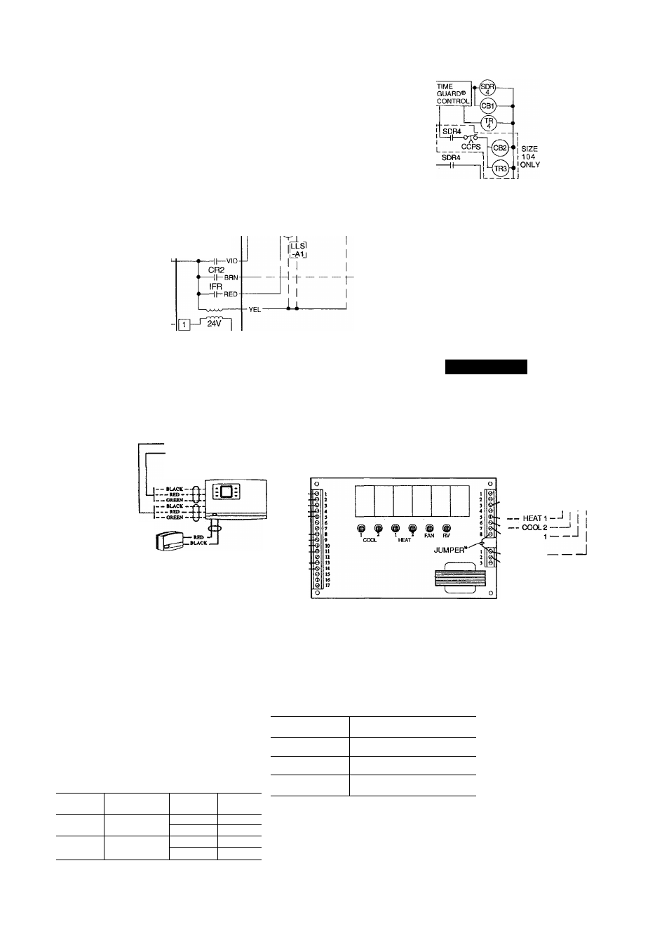
Internal TSR-01 relay contacts are rated for 1 amp/24 vac.
— — — — = = — — — —
- COMMUNICATION OUT
- COMMUNICATION IN
CARRIER COMMUNICATING
TEMP MONITOR THERMOSTAT
.(MODEL MS(T)01ES)
---------- WHITE-
-
-----RED —
--BLUE-
.+ -YEUDW.
— GREEN -
REMOTE ROOM
TEMP SENSOR
*To control heating device and provide automatic indoor-
fan operation on heating.
fJumper removed only when separate 24-v transformer power
source is used to power the TSR-01 relay pack
NOTES:
1
Liquid line solenoid valve LLS-A1 is used for solenoid
drop on circuit A Liquid line solenoid valve LLS-B1 is
used for solenoid drop for circuit B.
2
Solenoid drop is a safety feature which prevents refrig
erant migration to the compressor during the OFF cycle.
It is recommended on all systems and required on sys
tems where piping exceeds 75 ft (22 9 m) in length
3 The TSR-01 relay pack requires 10 va.
4
Factory wiring is in accordance with NEC; field modi
fications or additions must be in compliance with all ap
plicable codes
5
Wiring for field power supply must be rated 75 C mini
mum Use copper, copper-clad aluminum, or alumi
num conductors. Maximum incoming wire size for each
terminal block is 500 kcmil
6
Terminal blocks are for external field control connec
tions Control connections must be class 1 wiring
7
Field-supplied
components
(IFC,
LLS-A1,
and
LLS-B1) must have a maximum sealed coil rating of
30 va each (0 25 amp at 120 vac and 0 13 amp at
230 vac) Thermostats must have a minimum pilot duty
rating as follows:
----------
fan
1
------ COOL
-24 VAC (R)
-24 VAC (Common)----------- 1
TSR-01 RELAY PACK CIRCUIT BOARD
8 Replacement of factory wires must be with type 105 C
wire or its equivalent
9 Field-supplied liquid line solenoid valves installed at the
evaporator are required on all units
10
Units 38AH094 has 140 va and unit 38AH104
has 130 va of power available for field-installed
accessories
11
To minimize voltage drop, the following wire sizes are
recommended:
38AH
VA
(Ea Stage)
AMPS
VAC
094
275
2.29
120
1 15
240
104
325
2 70
120
1 35
240
LENGTH —
Ft(M)
INSULATED WIRE — AWG
(35 C Minimum)
Up to 50
(15.2)
No. 18
50-75
(15.2-22.9)
No 16
More Than 75
(22.9)
No 14
LEGEND
AWG
— American Wire Gage
C
— Compressor Contactor
CCPS
— Capacity Control Pressure
Switch
CR
— Control Relay
HD
— Heating Device
IFC
— Indoor-Fan Contactor
IFR
— Indoor-Fan Relay
kcmil
— Thousand Circular Mils
LLS
— Liquid Line Solenoid
NEC
— National Electrical Code
(U S.A Standard)
R
— Heating Relay (field-
supplied 24-v sealed coil,
10 va maximum rating)
RV
— Reversing Valve
SDR
— Solenoid Drop Relay
TB
— Terminal Block
TR
— Timer Relay
Factory Wiring
------------- Field Wiring
Fig. 22 — Field Wiring, One 2-Stage Thermostat — Units 38AH094 and 104
30