38ah044-084 dual-circuit and 38ah094-134 units, ~-r . -i – Carrier 38AH044-134 User Manual
Page 14
Attention! The text in this document has been recognized automatically. To view the original document, you can use the "Original mode".
To achieve good mixing of the refrigerant leaving the evapo
rator suction header for proper sensing by the TXV bulb:
1. Install a minimum of two 90-degree elbows upstream of
the TXV bulb location. See Fig. 14 (for 38AH044-084
dual-circuit and 38AH094-134 units) or Fig. 15 (for
38AH044-084 optional single-circuit units).
2. Locate the TXV bulb on a vertical riser, where possible.
If a horizontal location is necessary, secure the bulb at
approximately the 4 o’clock position.
3. Size the suction line from the evaporator to the common
suction line to achieve high refrigerant velocity. See
Tables 6A or 6B through 9A or 9B and Fig. 13.
If an oil return connection at the bottom of the suction
header is supplied with an evaporator, tee-in this connection
ahead of first mixing elbow. See Fig. 14 (for 38AH044-084
dual-circuit and 38AH094-134 units) or Fig. 15 (for 38AH044-
084 optional single-circuit units). When the compressor is
below the evaporator, the riser at the evaporator should ex
tend to the top of the evaporator section. After the riser is
installed, the suction line can elbow down immediately.
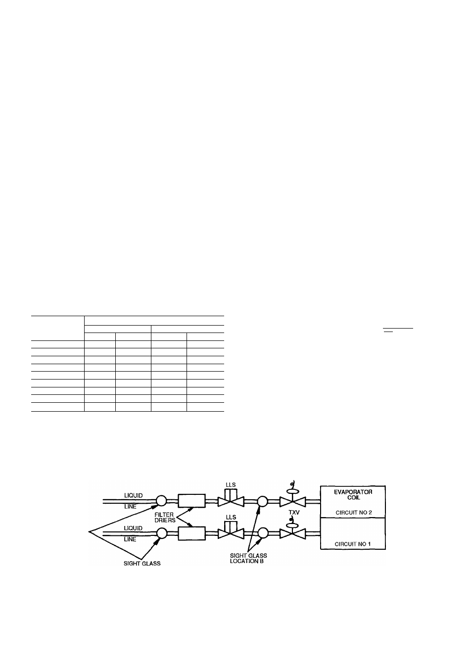
Install a field-supplied filter drier and sight glasses in each
refrigerant system. Select the filter drier for maximum unit
capacity and minimum pressure drop. Figure 11 (for 38AH044-
084 dual-circuit and 38AH094-134 units) or Fig. 12 (for
38AH044-084 optional single-circuit units) shows required
location of solenoid valves and recommended locations for
the filter driers and sight glasses. Complete the refrigerant
piping from the evaporator to the condenser before opening
the liquid and suction lines at the condenser.
Table 5 — Liquid Lift
MAXIMUM LIQUID LIFT
UNIT 38AH
60 Hz
50 Hz
Ft
M
Ft
M
044
69
21 0
57 5
175
054
75
23 0
75 0
23 0
064
75
23 0
65 0
19 8
074
45
137
37 5
11 4
084
75
23 0
75 0
23 0
094
55
167
46 0
140
104
50
152
42 0
128
124
75
23 0
65 0
19.8
134
45
137
37 5
11 4
UNITS 38AH044-084 — Relieve the pressure caused by the
holding charge into a refrigerant recovery system. Uneap the
suction line and cut the run-around tube at the liquid line
as close to the loop elbow as possible. This will leave ap
proximately 2 , in. (50 mm) of straight tube for liquid line
connection.
IMPORTANT: Protect the liquid valves from the heat
of brazing.
Leak test the entire system by using soap bubbles and
nitrogen or R-22 with an eleetronic leak detector.
Purge nitrogen or reclaim R-22 from system after comple
tion of leak-checking procedure. Repair leak if one is found.
When finished, evacuate and dehydrate system using the meth
ods described in Carrier GTACII (General Training Air Con
ditioning II), Module 4, System Dehydration.
UNITS 38AH094-I34 — Relieve the R-22 holding charge
of each circuit into a refrigerant recovery system. Remove
the liquid line to factory-installed suction line loop by cut
ting the loop at the liquid valve. (See diagram below and
Fig. 9.) Cut as close to the 90-degree bend in the loop as
possible. The remaining tube piece in the valve will be used
for brazing the liquid line. Unbraze and remove the cap from
the liquid line. For 38AH094 and 104 units, sweat-connect
the liquid and suction lines from the evaporator. For 38AH124
and 134 units, see Piping Kit Connections on page 21.
TOP VIEW
SUCTION
LINE
FACTORY-INSTALLED
SUCTION LINE LOOP
LIQUID
1---~-r . -I-
r _ r LINE
-CUT LINE
LEGEND
TXV
LOCATION A
LLS
— Liquid Line Solenoid
TXV
— Thermostatic Expansion Valve
Fig. 11 — Required Location of Soienoid Valves and Recommended Filter Drier and Sight Glass Locations for
38AH044-084 Dual-Circuit and 38AH094-134 Units.
14