Fig. 13 — double suction riser construction – Carrier 38AH044-134 User Manual
Page 15
Attention! The text in this document has been recognized automatically. To view the original document, you can use the "Original mode".
SIGHT GLASS
THERMOSTATIC
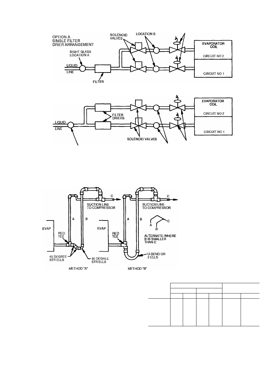
EXPANSION VALVES
DRIER
OPTION B
DUAL FILTER
DRIER ARRANGEMENT
SIGHT GLASS
LOCATION A
SIGHT GLASS
LOCATION B
THERMOSTATIC
EXPANSION
VALVES
Fig. 12 — Required Location of Soienoid Vaives and Recommended Fiiter Drier and
Sight Giass Locations for 38AH044-084 Optionai Single-Circuit Units
u
\
■ CONDENSING
\
------- 1—UNIT
3 FT MAX (914 mm)
LEGEND
A
— Pipe A, Suction Riser, without Trap
B
— Pipe B, Suction Riser with Trap
C
— Suction Line to Condensing
Unit
D
— Pipe D, Suction
Riser Short Lift
RED.
— Reducer
STR
— Street
NOTES-
1
Short riser, pipe D, is used when routing suction iine to condens
ing unit connection See table at right
2. See Tables 7A, 7B, 9A, and 9B for values of A, B, and C.
PIPE D DIAMETER
UNIT
38AH
Dual Circuit*
Singie Circuit*
A
B
in.
mm
in.
mm
in.
mm
044
1%
41
1%
41
21/8
54
054
1%
41
1%
41
21/8
54
064
1%
41
21/8
54
21/a
54
074
21/0
54
21/8
54
21/8
54
084
21/8
54
21/8
54
2%t
67t
094, 104
21/8
54
21/8
54
—
—
124, 134
2%
67
2%
67
—
—
‘Maximum iength of riser is 3 ft (914 mm).
tDouble suction riser required if accessory
instaiied
unioader is fieid
Fig. 13 — Double Suction Riser Construction
15