Step 3 — make refrigerant piping connections, A caution – Carrier 38AH044-134 User Manual
Page 13
Attention! The text in this document has been recognized automatically. To view the original document, you can use the "Original mode".
Step 3 — Make Refrigerant Piping
Connections
A CAUTION
The field-supplied liquid line solenoid valve must be in
stalled at the evaporator to avoid possible compressor
damage during unit operation. See Fig. 11 (for 38AH044-
084 dual-circuit and 38AH094-134 units), or Fig. 12 (for
38AH044-084 optional single-circuit units).
The units have large suction lines to minimize friction losses.
The units also have the ability to operate at low capacity.
Because of these capabilities, use special care with suction
piping and suction risers to ensure proper compressor oil
return under all operating conditions. Maximum allowable
vertical separation between the condensing unit and the evapo
rator is shown in Table 5. Size suction lines in accordance
with Tables 6A or 6B through 9A or 9B and Fig. 13. Mount
liquid line solenoid valve just ahead of the TXVs (thermo
static expansion valves) which will be mounted at the
evaporator. See Fig. 11 (for 38AH044-084 dual-circuit and
38AH094-134 units) or Fig. 12 (for 38AH044-084 optional
single-circuit units).
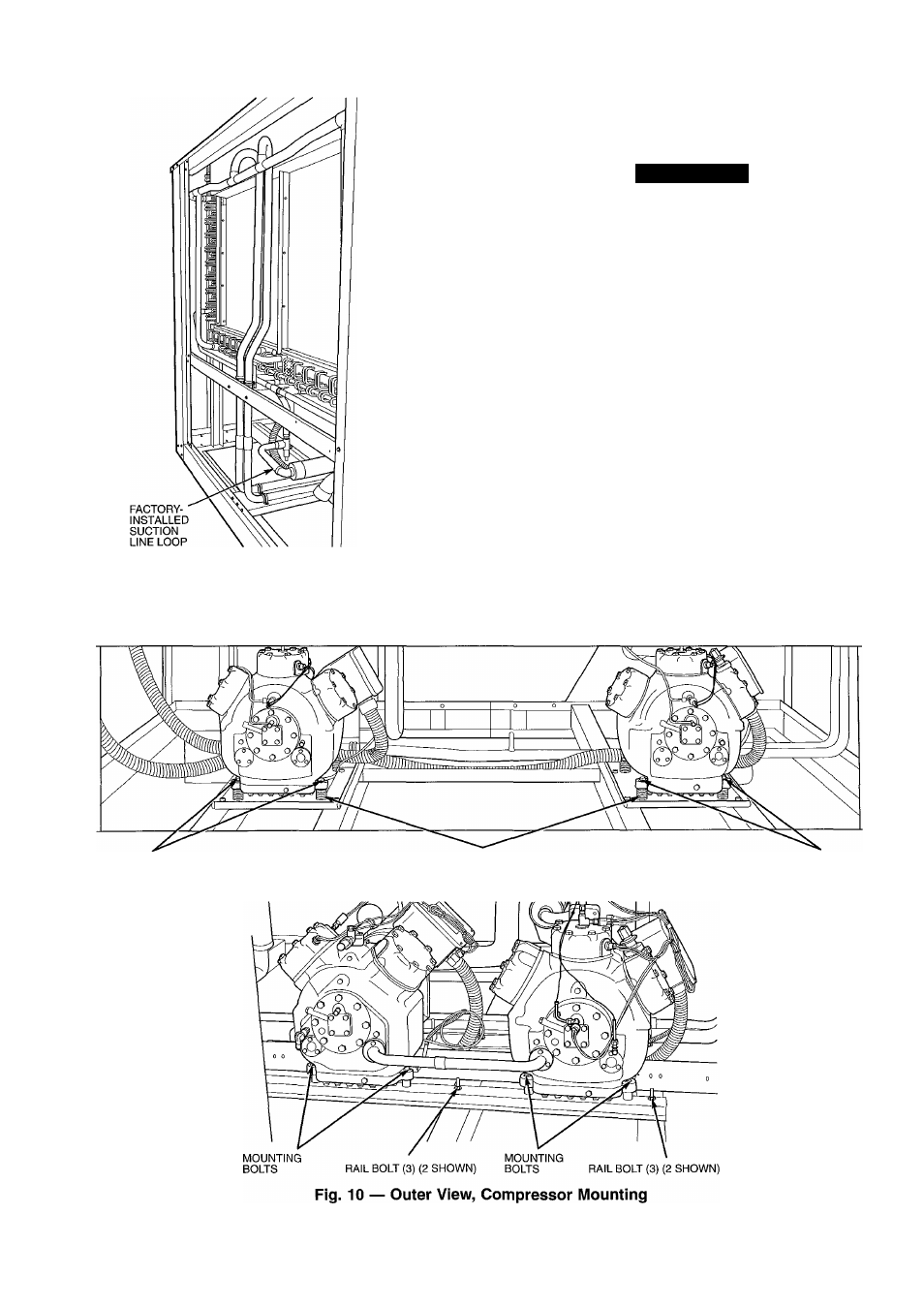
Fig. 9 — Typical Module with Cover Panels
Removed
38AH044-084,124,134
SHIPMENT BOLTS
MOUNTING SPRINGS
38AH094,104
SHIPMENT BOLTS
13