Carrier 38AH044-134 User Manual
Page 47
Attention! The text in this document has been recognized automatically. To view the original document, you can use the "Original mode".
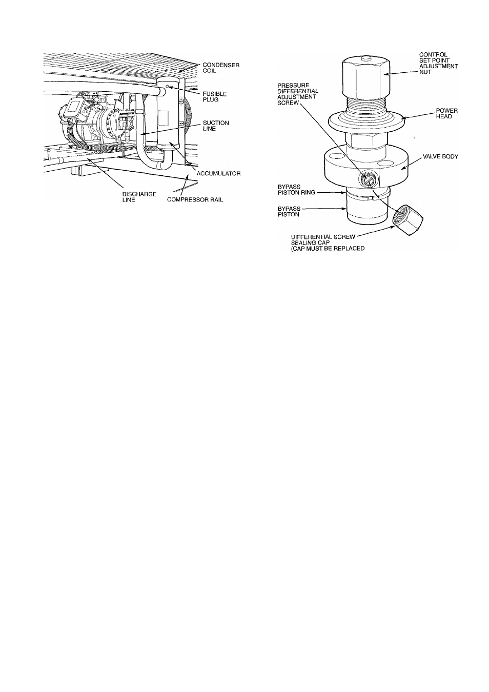
Fig. 45 — Accumulator and Fusible Plug
Timer Functions — (See Timer Cycle, Fig. 47.) Each
refrigeration circuit is controlled by an independent timer
which allows for the independent operation of each refrig
eration circuit.
NOTE: Unit 38AH044-084 optional single-circuit units have
one timer which controls the lead compressor. Lag compres
sor is controlled by CCPS (capacity control pressure switch).
SWITCH A — The timer is energized through contacts A-Al
or A-A2. This establishes the Time Guard® function which
prevents compressor short-cycling. Start of compressor is de-
i
layed approximately 5.5 minutes after shutdown.
^' SWITCH B — The compressor is initially energized through
contacts B-Bl.
SWITCH D — Contacts D-Dl provide a 2*/2-minute bypass
of the low-pressure switch at start-up for winter-start con
trol. On 38AH044-084 optional single-circuit units, contacts
D-D2 control start-up of compressor A2.
SWITCH E — Contacts E-EI provide a 40-second bypass
of the oil pressure switch at start-up. If oil pressure does not
build to the required minimum pressure in 40 seconds, the
compressor shuts down and the control circuit locks out.
On 38AH044-084 dual-circuit and 38AH094,104 units, lag
circuit B start-up is delayed 60 seconds after a call for cool
ing is made to the circuit. This prevents compressor(s) in
both lead and lag circuits from starting at the same time.
Control Circuit Reset — The control circuit locks out
if the unit shuts down because of low oil pressure, high dis
charge gas temperature (DGT), or excessive high-side pres
sure. To reset the control circuit, open and close the fan cir
cuit breaker (FCB). This resets the timer, and the unit restarts
under Time Guard control. At start-up, if the low-pressure
switch (EPS) does not close after 2'/2 minutes, the unit shuts
down. When the pressure builds enough for the EPS to cut
in, the control circuit is energized automatically and start-up
proceeds under Time Guard control.
TO PREVENT REFRIGERANT LEAKAGE)
Fig. 46 — Pressure-Actuated Capacity Control Valve
CONTROL
Sequence of Operation — Units are controlled with
electromechanical components. Each refrigeration circuit
(except 38AH044-084 optional single-circuit units) is oper
ated by an independent timer which controls the operation
sequence of each circuit.
On a call for cooling, first stage cooling thermostat TCI
closes. Condenser fans and timer (TM) are energized. After
approximately 7 seconds, timer contacts E-El close. Ap
proximately 12 seconds after TCI closes, normally-open timer
contacts B-B1 close for 1 second. This energizes compres
sor A1 contacts CAl and starts the compressor. At the same
time, solenoid drop relays (SDRs) and liquid line solenoid
valve no. 1 (EES-A for 38AH044-084 dual-circuit units;
EES-Al for all other units) open, and timer relay no. 1 (TR2)
is energized. Normally open TR2 contacts close, completing
a circuit around B-Bl and through compressor A1 contac
tors to maintain compressor operation when B-Bl contacts
open. Contacts E-El remain closed for approximately 40 sec
onds to bypass the oil pressure switch (OPS). If oil pressure
is insufScient when contacts E-El open, the compressor stops,
the timer cycles off, and the control circuit locks out. At start
up, timer contacts D-Dl are closed, bypassing low-pressure
relay contacts EPR-A for 21/2 minutes. This provides a win
ter start-up feature.
Approximately 2V2 minutes after TCI closes, timer con
tacts D-Dl open and D-D2 close. If pressure is insufficient
to close the low-pressure switch, the low-pressure switch re
lay is open, the compressor shuts down, and the Time Guard
control is initiated. (Time Guard control prevents compres
sor from restarting for 5 minutes after the demand for cool
ing is satisfied.)
47