3 external correction input, M a in separate g ps r eceiver – TeeJet RX 400p User Manual
Page 141
RX 400p
9-3 98-05044
R1
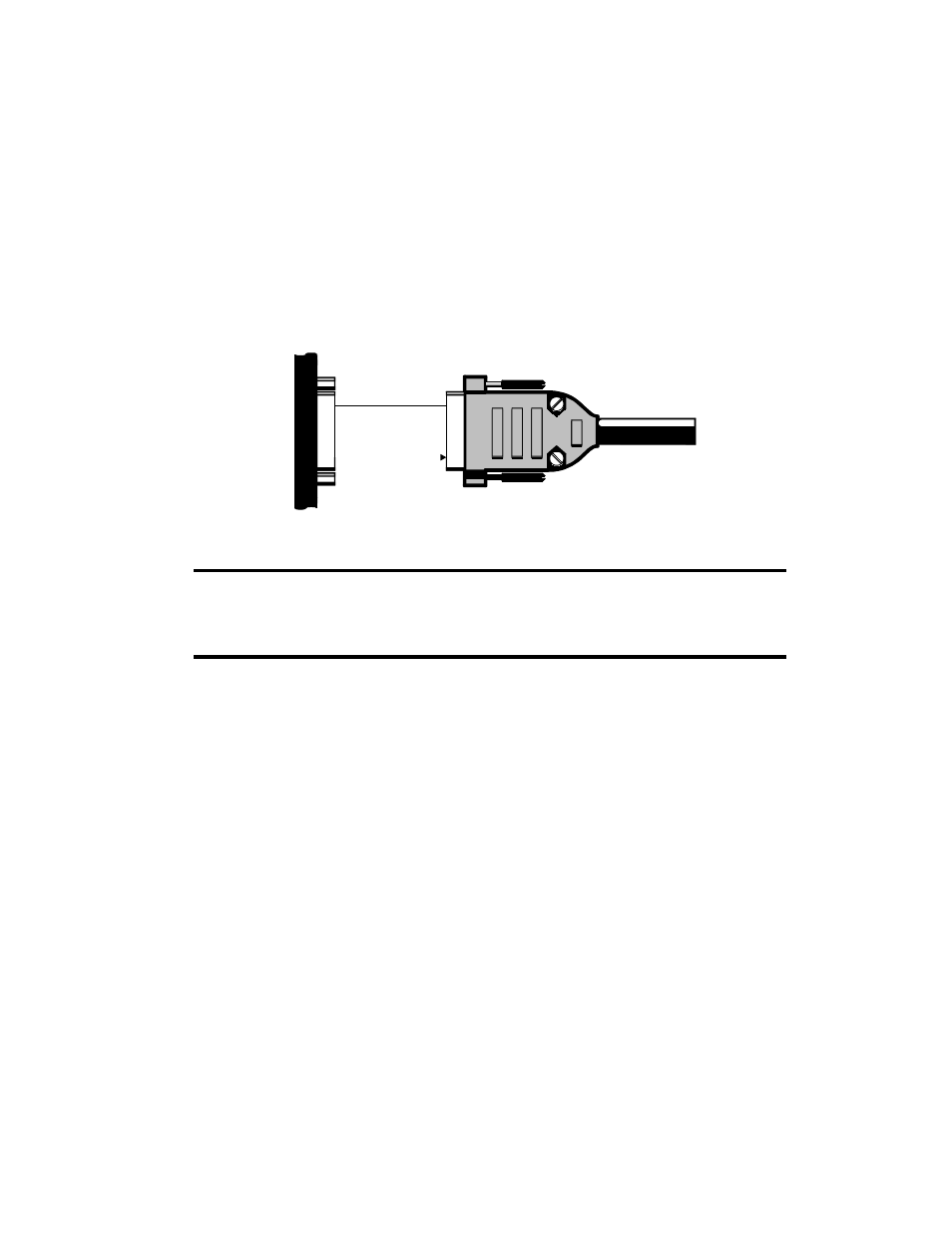
Figure B-2 illustrates the required interface between the RX 400p and a separate GPS
receiver:
2 TX
RTCM
5 GND
GND
RX
M A IN
Separate G PS R eceiver
Figure B-2 RTCM Data Interface
Note - For successful communications, the baud rate of the RX 400p MAIN port
must be set to match that of the separate GPS receiver. Additionally, you must
interface the RX 400p to an RS-232C serial port of the separate GPS receiver.
Refer to Section 4.15.3 for instructions related to setting the RX 400p baud rate.
9.3 External Correction Input
In this operating mode, an external correction device inputs RTCM correction data
through the RX 400p’s RTCM In port (AUX port). In order to accomplish this, the
RX 400p must be operating in the external RTCM input DGPS mode.
To establish communications between the RX 400p and an external GPS receiver,
you must:
Connect Pin-3-receive (RX) of the AUX port to transmit pin (TX) of the external
correction source
Connect Pin-5-Common Ground of the AUX port to the signal return or common ground
of the external correction source