3 condenser fans 3.4 coil maintenance, 0 maintenance and service procedures (cont'd), 4 coil maintenance – Reznor MAPS - A,B,C Users Manual User Manual
Page 8: 3 condenser fans, 2 drive components cont'd)
Form O-MAPSIII&IV Cabinets A/B/C, Page 8
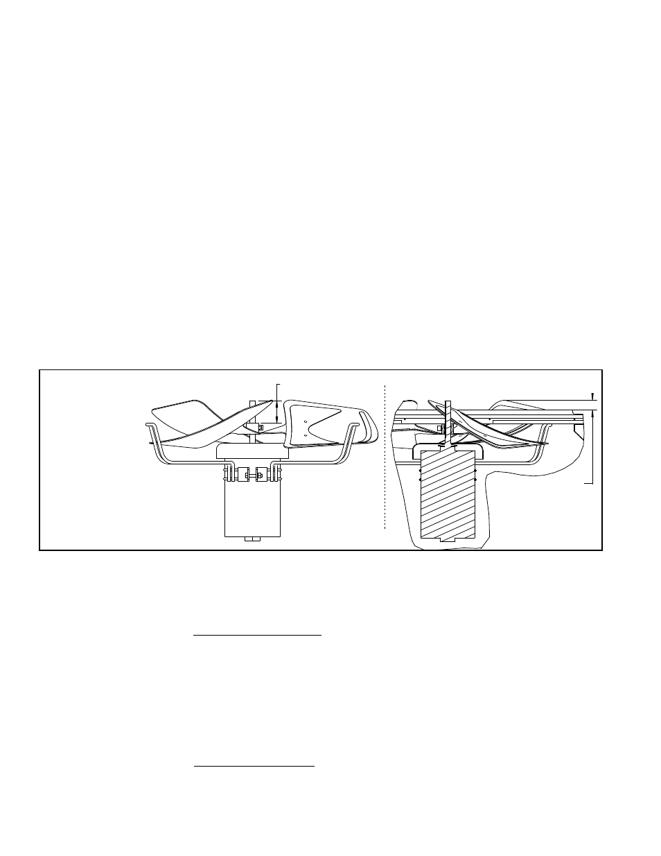
2-1/2” (63.5mm)
Fan and Motor Assembly
showing Fan Blade Position
Cross-section of Installed Fan and Motor
Assembly showing Cabinet Top
1.76” (44.7mm)
Top of Fan Blade
to Top of the
Cabinet Top Panel
Fan rotation is
clockwise.
FIGURE 3 -
Condenser
Fan Assembly
Dimensions
and Rotation
3.4 Coil
Maintenance
The MAPS
®
cooling system is equipped with space-saving MACROCHANNEL
®
coils.
Inspect all cooling system coils at the beginning of the cooling season or more often if
needed. Follow the cleaning instructions below. If additional cleaning is required or if a
coil must be removed for any reason, consult the factory. Be prepared to provide rating
plate and specific installation information.
Condensing Coil Access - The condensing coils are visible on the side of the unit
(below the condenser fans). For additional access for inspection and maintenance,
remove the tubing access panel (See
FIGURE 1, page 5.).
3.0 Maintenance
and Service
Procedures
(cont'd)
3.3 Condenser Fans
Depending on the size, there are two, three, or four fans in the condenser section. If
parts need to be replaced, use only factory authorized replacement parts. See
FIGURE
3 for assembled dimensions and proper fan rotation.
Condenser
Coil Cleaning
Instructions:
1. Verify that the electrical power has been turned off and the disconnect switch locked.
2. Use a soft brush to remove any dirt and debris from the coils.
3. Spray with cold or warm (not hot) water and a cleaning solution (non-acid based coil
cleaner is recommended). Due to possible damage to the coil, DO NOT use high
pressure spray.
4. When clean, rinse with cool, clean water.
Evaporator Coil Access - The evaporative coils can be accessed by opening the coil
cabinet door.
Inspect coils for debris, dirt, grease, lint, pollen, mold, or any element which would
obstruct heat transfer or airflow. Inspect coils and tubing for physical damage. Inspect
Belts (cont'd) - Blower systems are equipped with either Power Twist Plus
®
linked
blower belt or a solid belt. The linked belts are designed in sections allowing for easy
sizing and adjustment. The belt is sized at the factory for the proper tension. If the belt
needs adjustment, the recommended method of shortening the belt length is to count
the number of links and remove one link for every 24. (A link is made up of two joining
sections of belt. For easier removal of links, turn the belt inside out. But be sure to turn
it back before installing.)
If equipped with a solid belt, adjust the belt tension by turning the adjusting screw on
the motor base until the belt can be depressed 1/2" (13mm) on each side. After correct
tension is achieved, re-tighten the locknut on the adjustment screw.
Proper belt tension is important to the long life of the belt and motor.
Be sure belts are aligned in the pulleys. If a belt is removed or replaced, be sure the
directional arrows on the belt match the drive rotation.
Motor and Blower - Inspect the motor mounts periodically. Remove dust and dirt accu-
mulation from the motor and wheel.
The blower has cast iron, pillowblock, sealed bearings. Under most operating condi-
tions, re-lubrication is unnecessary. If lubrication is required, use a lubricant compat-
ible to Shell Alvania #2 (lithium base - Grade 2). Operating temperature range is -30
to 230°F.
If any drive parts need to be replaced, use only factory-authorized replacements
designed for the application.
3.2 Drive
Components
Cont'd)