7 thermostatic expansion valves, Figure 6 - thermostatic expansion valve – Reznor MAPS - A,B,C Users Manual User Manual
Page 19
Form O-MAPSIII&IV Cabinets A/B/C, P/N 257004R8, Page 19
c) If the test for acid is negative, remove the suction line filter drier, replace
the liquid line drier, evacuate, and re-charge the system with the recovered
refrigerant.
If the test indicates acid, replace both the liquid line filter drier and the suction
line filter drier and repeat b) and c).
CAUTION: After cleanup is complete, remove the suction line filter
drier. See Hazard Levels, page 3.
d) Verify subcooling and superheat (refer to
Step 11).
e) When the system is operating properly, remove the gauges.
Or, IF the oil measured in Step 2 was not significantly less than that
shown in the table on page 14 or the acid test in
Step 2 did not indicate
a compressor burnout, continue to the review in
Step 13.
•
Step 13 . Review ALL Steps to ensure that nothing was overlooked.
3.7 Thermostatic
Expansion
Valves
Cabinet
Size
RCB/
RDCB/
RECB
RDB/
RDDB/
REDB
Thermostatic Expansion Valve P/N's by
Compressor Circuit
A
B
C
DH (Reheat)
A
060
084
220553
220552
--
220552
A or B
078
102
220554
220552
--
220552
090
114
220554
220553
--
220552
118
142
220555
220553
--
220552
136
162
220555
220554
--
220552
B
160
184
220555
220554
220552
220552
186
210
220554
220555
220554
220552
222
220553
200
224
220554
220555
220555
220552
236
220553
C
190
248
234987
220558
N/A
234987
262
234987
216
272
220558
220555
234987
288
234987
298
354
220558
220558
234987
370
234987
410
468
220558
220558
220558
234987
482
234987
Compressor B
Compressor C
Compressor A
Compressor
Dh (Reheat)
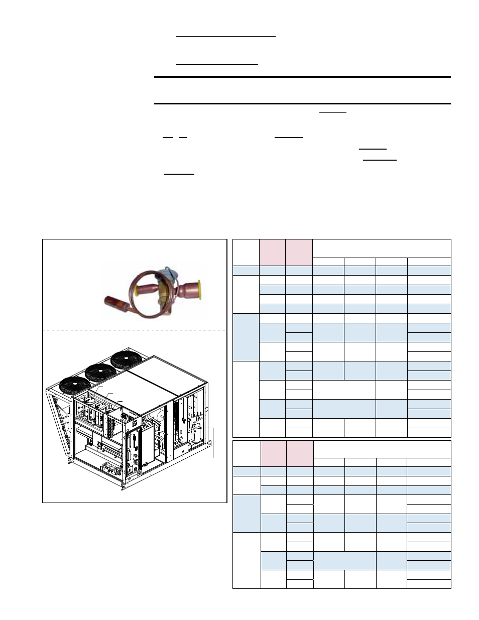
All refrigeration circuits have a thermostatic expansion valve. Thermostatic expansion
valves do not have replaceable parts. If a replacement valve is required, it must be
for R410-A refrigerant and must be sized correctly for the application. All refrigerant
service should be performed by a service technician qualified in R410-A refrigerant.
Replacement valve P/N's by Model, size, and circuit are listed in the following tables.
Cabinet
Size
RCC/
RDCC/
RECC
RDC/
RDDC/
REDC
Thermostatic Expansion Valve P/N's
by Compressor Circuit
A
B
C
DH (Reheat)
A
060
084
N/A
220554
N/A
220552
A or B
090
114
N/A
220555
N/A
220552
120
144
220554
220554
N/A
220552
B
160
184
220555
220555
N/A
220552
196
220553
200
236
220554
220556
220554
220553
257
234967
C
190
248
234967
261175
N/A
234987
262
234987
298
354
261175
261175
234987
370
234987
410
468
261175
261175
261175
234987
482
234987
FIGURE 6 - Thermostatic Expansion
Valve